Ring gear, gear device and mold for manufacturing the ring gear

Active Publication Date: 2018-02-22
JOHNSON ELECTRIC INTERNATIONAL AG
View PDF0 Cites 3 Cited by
  • Summary
  • Abstract
  • Description
  • Claims
  • Application Information

AI Technical Summary

Benefits of technology

[0027]The compound ring gear of the present invention is integrally formed into a single piece in a single mold cavity. Assembly of the first ring gear part and the second

Problems solved by technology

The ring gears fabricated in this manner require secondary machining and subsequent mechanical connection and thus have a

Method used


Image

  • Ring gear, gear device and mold for manufacturing the ring gear
  • Ring gear, gear device and mold for manufacturing the ring gear
  • Ring gear, gear device and mold for manufacturing the ring gear

Examples


Embodiment Construction

[0039]Below, embodiments of the present invention will be described further with reference to the accompanying drawings.

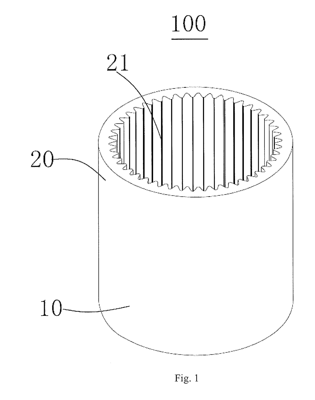
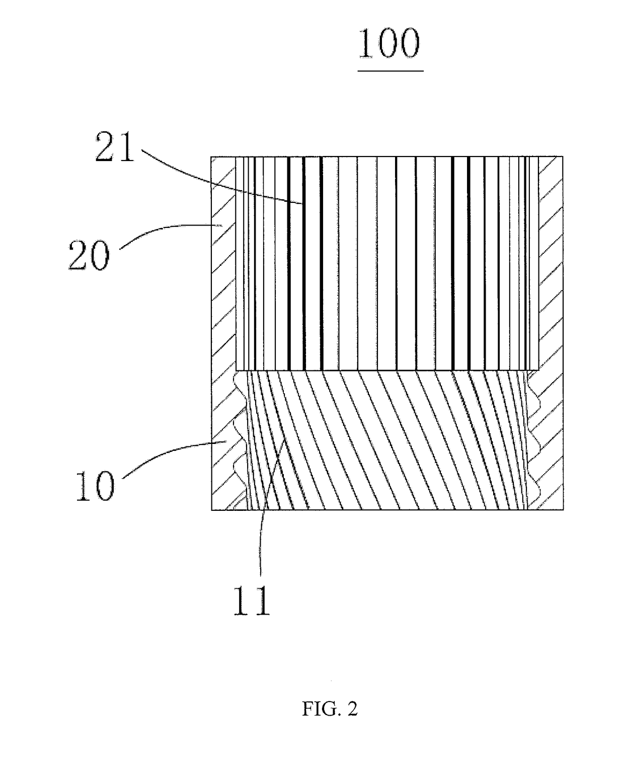
[0040]Referring to FIG. 1 and FIG. 2, the present invention provides a ring gear 100 made from a powder metallurgy material. Narrow and long pores are formed between powder metallurgy particles of the ring gear 100, and a maximum size of long sides of the narrow and long pores is less than 0.2 mm. In this embodiment, the ring gear 100 is a compound ring gear including a first ring gear part 10 and a second ring gear part 20. The first ring gear part 10 comprises a first annular body and a plurality of first teeth 11 formed on the inner surface of the first annular body. The second ring gear part 20 comprises a second annular body and a plurality of second teeth 21 formed on the inner surface of the second annular body. The first ring gear part 10 and the second ring gear part 20 are integrally formed. That is, the first and second annular bodies, the first teeth 11...


PUM

PropertyMeasurementUnit
Fractionaaaaaaaaaa
Angleaaaaaaaaaa
Sizeaaaaaaaaaa

Abstract

The present invention provides a ring gear and a gear reduction device. The ring gear includes a one-piece annular body made from powder metallurgy material, and a first ring gear part and a second ring gear part formed on a surface of the annular body. The first ring gear part and the second ring gear part are arranged along an axial direction of the annular body. The ring gear has a density less than 92% of its theoretical density and a mass of 6.0 to 8.0 grams per cubic millimeter. The present invention further provides a mold for manufacturing the ring gear. The ring gear of the present invention includes two ring gears integrally formed at once, and the two ring gears have improved concentricity.

Description

CROSS REFERENCE TO RELATED APPLICATIONS[0001]This non-provisional patent application claims priority under 35 U.S.C. §119(a) from Patent Application No. 201710449138.3 filed in The People's Republic of China on 14 Jun. 2017 and Patent Application No. 201610704012.1 filed in The People's Republic of China on 22 Aug. 2016.FIELD OF THE INVENTION[0002]This invention relates to the field of gears, and in particular to a ring gear and a gear device using the ring gear.BACKGROUND OF THE INVENTION[0003]In a conventional two-stage gear reduction device, a ring gear of a first planetary gear train and a ring gear of a second planetary gear train are usually separately formed. In general, each ring gear has connection portions which are machined after the ring gear is formed, and the connection portions of the two ring gears are connected together via fasteners such as screws or pins. The ring gears fabricated in this manner require secondary machining and subsequent mechanical connection and ...

Claims


Application Information

Patent Timeline
IPC IPC(8): F16H1/46F16H55/17F16H57/08B22F5/08B22F3/03
CPCF16H1/46F16H55/17F16H2055/176B22F5/08B22F3/03F16H57/08B21J5/025B21K1/30B21K1/305
Inventor TA, JING NINGLO, LAP WAHYI, XING JULI, QIU MEI
Owner JOHNSON ELECTRIC INTERNATIONAL AG
Why Eureka
Try Eureka