External device for measuring instrument

a technology of external devices and measuring instruments, applied in measurement devices, instruments, transmission systems, etc., can solve the problems of increased cost burden on both manufacturers and users, cumbersome cables, and increased operability, and achieve the effect of expanding the functions of measuring instruments

Active Publication Date: 2018-02-22
MITUTOYO CORP
View PDF9 Cites 2 Cited by
  • Summary
  • Abstract
  • Description
  • Claims
  • Application Information

AI Technical Summary

Benefits of technology

The present invention aims to provide an external device for a measuring device that can expand its functions without compromising operability. Currently, manufacturers and users have to prepare various types of external wireless communication devices for each type or size of small measuring instrument, which increases cost burden. The invention proposes an external device that can pivotally supported by a rotation axis, allowing the housing to be moved to a position where it does not interfere with the measurement. Overall, the invention provides an improved solution to expand the functionality of a measuring device without impacting its usability.

Problems solved by technology

However, the cable is cumbersome and thus operability is also hindered.
However, various types of external wireless communication devices have to be prepared for each of types or sizes of small measuring instruments, and thus cost burden on both manufacturers and users is increased.

Method used


Image

  • External device for measuring instrument
  • External device for measuring instrument
  • External device for measuring instrument

Examples


first embodiment

[0035]The first embodiment of the present invention will be described with reference to FIGS. 1 to 6.

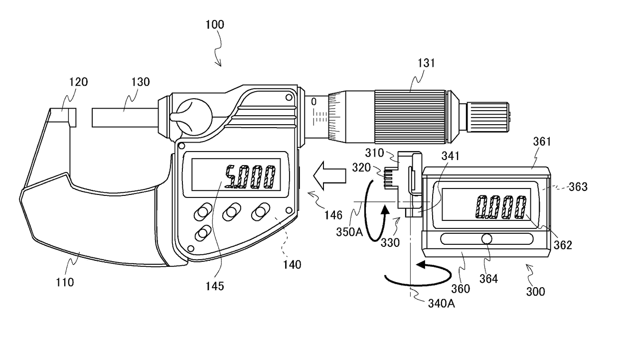
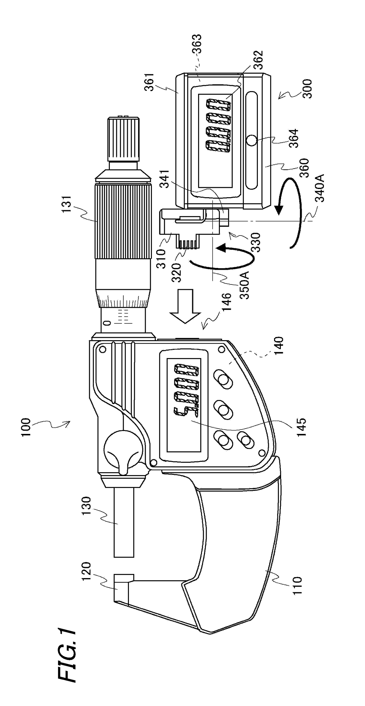
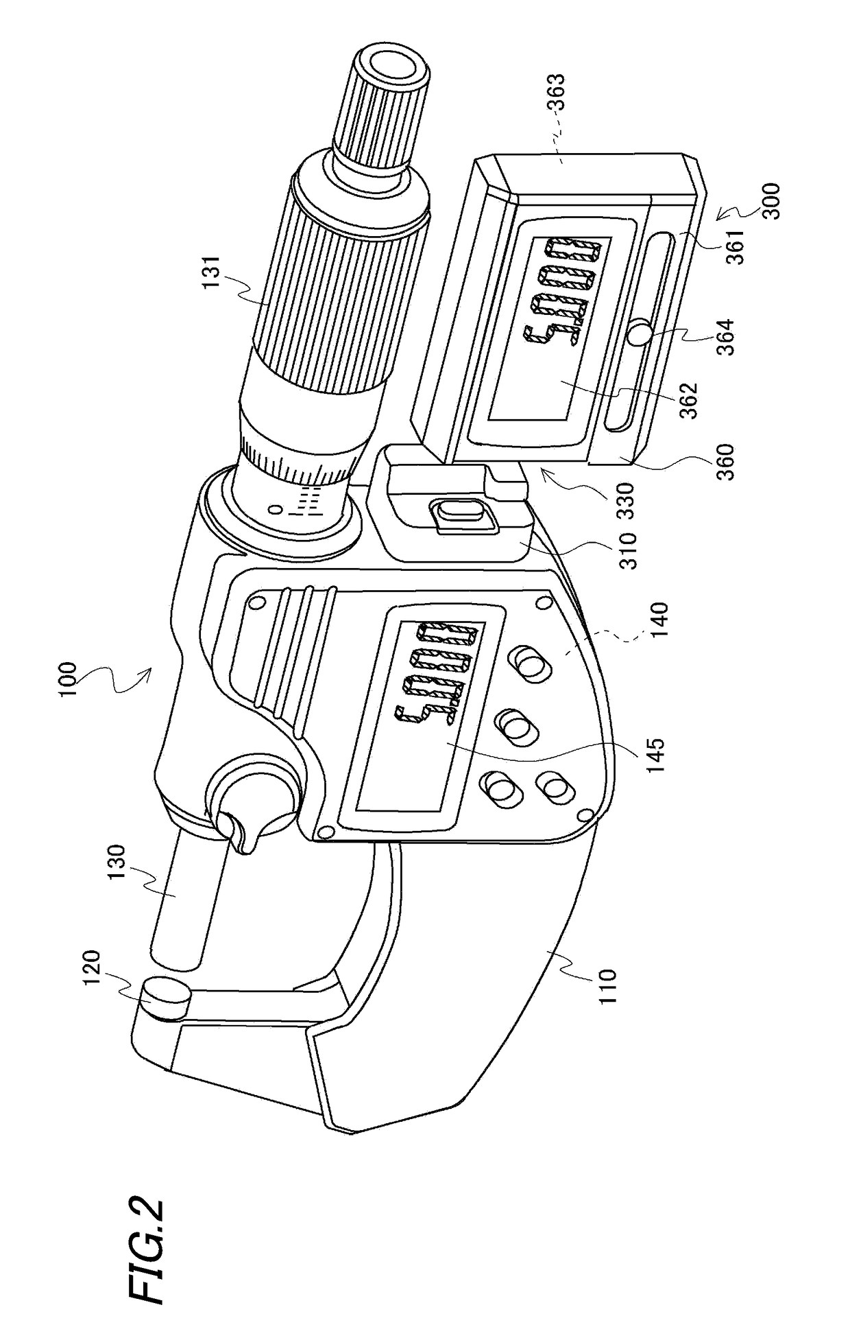
[0036]FIG. 1 is an exterior view of a digital type micrometer 100 and an external device 300 configured to be detachably attached to the micrometer 100.

[0037]The micrometer 100 includes a U-shaped frame 110, an anvil 120, a spindle 130 and an electric component unit 140.

[0038]The anvil 120 is arranged in one end of the U-shaped frame 110, and the spindle 130 is arranged on the other end of the U-shaped frame 110 so that the spindle 130 can move back and forth against the anvil 120.

[0039]When a thimble 131 is rotated with fingers, the spindle 130 is rotated together. The spindle 130 is configured to be moved back and forth by a feed screw. Also, an encoder (detecting means) (not shown) as a means for detecting an amount of rotation of the spindle 130 is provided on the other end of the U-shaped frame 110.

[0040]Herein, a measuring means is constituted of the U-shaped frame 110, the anv...


PUM


Abstract

An external device is configured to be detachably attached to a measuring instrument via a connector. The external device includes a connector part, an external device body part and a movable connection part. The connector part has a connection terminal. The external device body part has a display part on a side surface of the external device body part. The movable connection part is configured to connect the connector part with the external device body part. The movable connection part is a biaxial rotation hinge having two pivot axes which are in a twisted position relationship with respect to each other.

Description

CROSS-REFERENCE TO RELATED APPLICATION[0001]This application claims the benefit of Japanese Patent Application No. 2016-162294, filed on Aug. 22, 2016, the entire contents of which are hereby incorporated by reference, the same as if set forth at length, the entire of which are incorporated herein by reference.TECHNICAL FIELD[0002]The present invention relates to an external device configured to be detachably attached to a measuring instrument.BACKGROUND ART[0003]As small measuring instruments which allow a measurer to carry out measurement by hand, for example, a dial gauge, a vernier calipers and a micrometer are known. These small measuring instruments have been also multi-functionalized, and thus various functions such as a wireless communication function have been installed thereon.[0004]There are several types of multi-functionalized measuring instruments.[0005]A first type is a type in which various functions are equipped in a measuring instrument. For example, a wireless com...

Claims


Application Information

Patent Timeline
Patent Type & Authority Applications(United States)
IPC IPC(8): G01D7/00
CPCG01D7/00G01B3/18G01B3/205G01D13/00G01B21/047G08C17/00
Inventor NIWANO, ATSUYAHAYASHIDA, SHUJIHAYASHI, NOBUYUKIFUJIKAWA, YUJIMATSUMOTO, KOJI
Owner MITUTOYO CORP
Why Eureka
Try Eureka