Electronic device

a technology of electronic devices and electronic components, applied in the direction of instruments, multi-programming arrangements, program control, etc., can solve the problems of low replacement efficiency and effort, and achieve the effect of reducing labor costs and operating times

Inactive Publication Date: 2018-02-22
AOPEN
View PDF0 Cites 0 Cited by
  • Summary
  • Abstract
  • Description
  • Claims
  • Application Information

AI Technical Summary

Benefits of technology

[0006]According to embodiments, different operation parameters respectively corresponding to different thermal covers with different heat dissipation capacities can be preset in the BIOS. Accordingly, when the electronic device is assembled to a different thermal cover, (the BIOS can automatically select a corresponding operation parameter. Therefore, labor costs and operation times can be reduced.

Problems solved by technology

As a result, replacement of the heat dissipation housing takes efforts and efficiency for the replacement is low.

Method used


Image

  • Electronic device
  • Electronic device
  • Electronic device

Examples


first embodiment

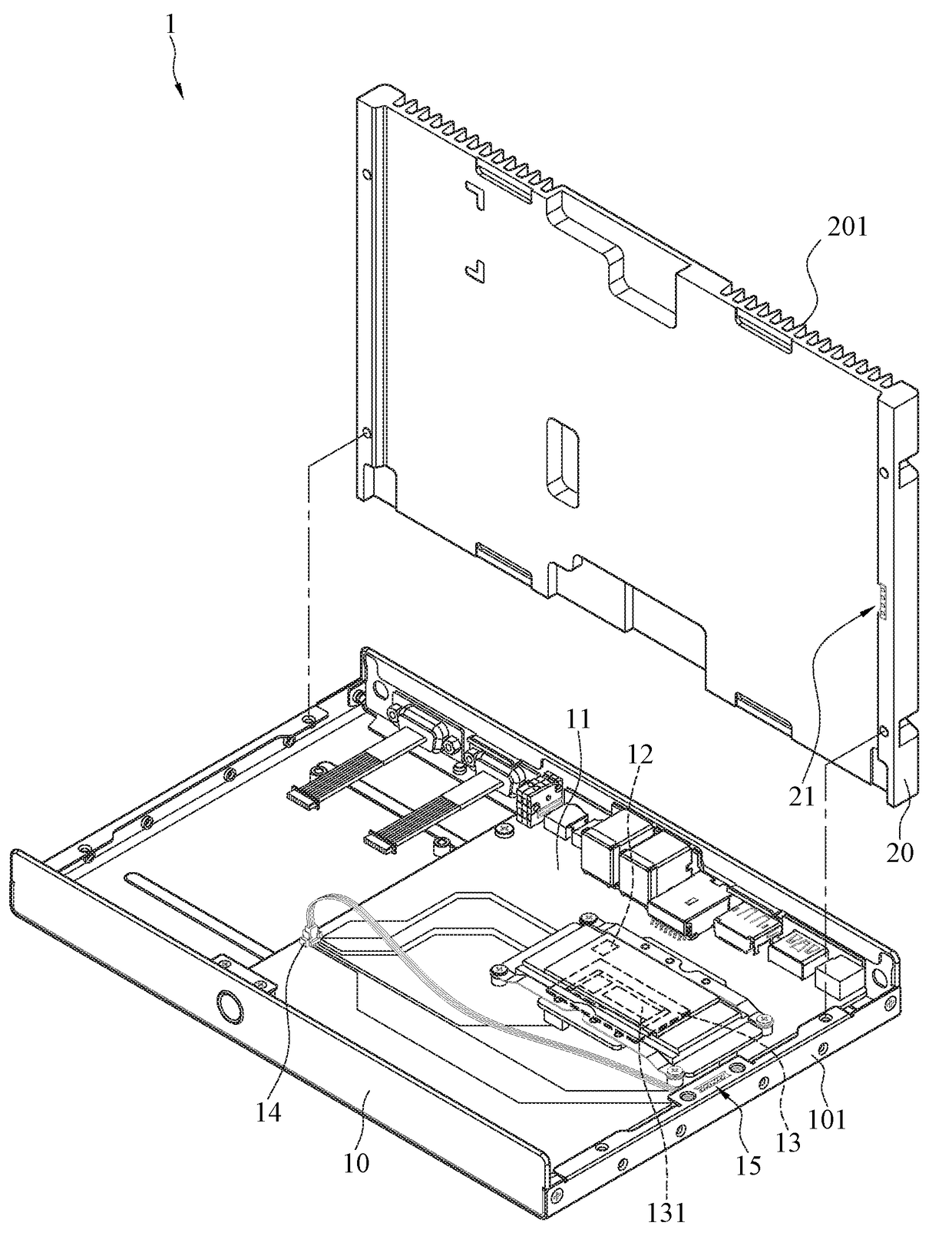
[0021]Please refer to FIGS. 1 and 3, respectively illustrating exploded views (1) and (2) of an electronic device according to the instant disclosure. The electronic device 1 may be a computer (an industrial computer or a personal computer). The electronic device 1 comprises a chassis 10, a first thermal cover 20, and a second thermal cover 30. The chassis 10 is assembled with a motherboard 11 and a recognition device 15. In this embodiment, the motherboard 11 is assembled in the chassis 10, and the recognition device 15 is assembled on one of the side boards 101 of the chassis 10. In some embodiments, the recognition device 15 may be assembled in the chassis 10. The motherboard 11 comprises a basic input / output system (abbreviated as BIOS 12) and an electronic component 13. The electronic component 13 may be a central processing unit (CPU), a display card, a memory, or a heat dissipation fan assembled on the motherboard 11. As shown in FIGS. 1 and 3, in this embodiment, an input / ou...

second embodiment

[0032]Please refer to FIGS. 5 and 6, illustrating partial sectional view (1) and (2) of an electronic device according to the instant disclosure. In this embodiment, the recognition device 15A comprises four conductive contacts 152. As shown in FIG. 5, the first triggering member 21A of the first thermal cover 20 comprises a first circuit board 211A, four first pogo pin connectors 213 are assembled on the first circuit board 211A and respectively correspond to the four conductive contacts 152, and two of the first pogo pin connectors 213 of the first triggering member 21A are electrically connected with each other to be in a conduction state (for example, two of the first pogo pin connectors 213 are connected with each other via a connection wire 41). As shown in FIG. 6, the second triggering member 31A of the second thermal cover 30 comprises a second circuit board 311A, four second pogo pin connectors 313 are assembled on the second circuit board 311A and respectively correspond t...

third embodiment

[0033]Please refer to FIGS. 7 and 8, illustrating partial sectional views (1) and (2) of an electronic device according to the instant disclosure. In this embodiment, the recognition device 15B comprises a receptacle connector 153. As shown in FIG. 7, the first triggering member 21B of the first thermal cover 20 comprises a first circuit board 211B and a first plug connector 214 fixedly assembled on the first circuit board 211B and corresponding to the receptacle connector 153. As shown in FIG. 8, the second triggering member 31B of the second thermal cover 30 comprises a second circuit board 311B and a second plug connector 314 fixedly assembled on the second circuit board 311B and corresponding to the receptacle connector 153. As shown in FIG. 7, when the first thermal cover 20 covers the chassis 10, the first plug connector 214 is correspondingly connected to the receptacle connector 153, and the first circuit board 211B outputs a first signal automatically. As shown in FIG. 8, w...


PUM


Abstract

An electronic device includes a chassis, a first thermal cover, and a second thermal cover. The chassis is assembled with a motherboard and a recognition device. The motherboard includes a basic input/output system (BIOS) and an electronic component. The BIOS is electrically connected to the electronic component. A first operation parameter and a second operation parameter adapted to the electronic component are preset in the BIOS. When the first thermal cover covers the chassis, the BIOS drives the electronic component to be operated according to the first operation parameter. When the second thermal cover covers the chassis, the BIOS drives the electronic component to be operated according to the second operation parameter.

Description

CROSS-REFERENCE TO RELATED APPLICATION[0001]This non-provisional application claims priority under 35 U.S.C. § 119(a) to Patent Application No. 105126466 filed in Taiwan, R.O.C. on Aug. 18, 2016, the entire contents of which are hereby incorporated by reference.BACKGROUNDTechnical Field[0002]The instant disclosure relates to an electronic device, in particular, to an electronic device capable of operating in a mode corresponding to the heat dissipating capacity of its thermal covers.Related Art[0003]Along with the developments of technology, needs for computers gradually increases. For example, industrial computers were utilized in controlling, monitoring, or test procedures of automated productions of factories in the early days; nevertheless, since technology marches, applications of industrial computers become wider, and industrial computers can be utilized in, e.g., point of sale (POS) terminals, Kiosks, automated teller machines (ATM), digital boards, ticket reader systems in M...

Claims


Application Information

Patent Timeline
Patent Type & Authority Applications(United States)
IPC IPC(8): G06F1/20G06F9/44G06F9/50
CPCG06F1/206G06F9/5094G06F9/4401G06F1/3206G06F1/20
Inventor WANG, JO-CHIAOCHENG, CHIH-TIENCHEN, CHIEN-HUIYANG, CHING-HUNG
Owner AOPEN
Why Eureka
Try Eureka