Magnetic chuck

a technology of chuck and chuck body, which is applied in the direction of magnets, magnetic bodies, manufacturing tools, etc., can solve the problems of inefficient waste of materials, high cost of cutting and grinding, and complicated production process, so as to reduce the number of cutting and grinding processing, simplify the assembly of parts, and reduce the production cost and production time

Inactive Publication Date: 2014-02-13
JIN YOUNG PRECISION MACHINE
View PDF5 Cites 14 Cited by
  • Summary
  • Abstract
  • Description
  • Claims
  • Application Information

AI Technical Summary

Benefits of technology

[0020]According to the present invention, by reducing a process and the number of cutting and grinding processing while manufacturing a magnetic chuck and by simplifying assembly of parts, a production cost and a production time can be reduced.
[0021]Further, according to the present invention, by providing a magnetic chuck that can be produced in a small size or a large size, the magnetic chuck can be easily used, as needed, and because a workpiece can be attached to a front surface of the magnetic chuck, a horizontal processing and a vertical processing of the magnetic chuck is available, and one side corner of the magnetic chuck is formed in an inclined surface inclined by a constant angle or a workpiece can be processed in a predetermined angle by attaching a jig in which an inclined surface is formed.
[0022]Further, according to the present invention, when attaching and detaching a workpiece by performing a heat treatment at one side of the magnetic chuck and when pulling and pushing to move a position of the magnetic chuck in a table and the bottom by providing a steel plate to the other side thereof, damage is prevented from occurring in the magnetic chuck, and a commercial value and precision are maintained, and the magnetic chuck can be used for a long term.

Problems solved by technology

Because the main body 140 of such a magnetic chuck forms the partition 144 using a milling machine and forms the receiving groove 142 by cutting in a predetermined size and depth, there was a problem that much time is consumed for a cutting processing and that a material is inefficiently wasted due to a chip generating upon processing.
In this way, because the conventional magnetic chuck is formed with a plurality of parts, there was a problem that the number of processing of coupling the plurality of parts is many and that a production process is complicated and that the magnetic chuck is produced for a long time and that a product cost thus increases.
Further, because a workpiece may be attached to only an upper portion of the top plate 120, a processing other than a horizontal processing was limited, and in a process of attaching and detaching the workpiece, damage such as a scar has occurred in an upper portion of the top plate 120, and a processing of grinding an upper portion of the top plate 120 is additionally necessary according to whether the top plate 120 is damaged, and particularly, because a thickness that can perform a grinding processing is small, there was a problem that a use period of the top plate 120 is short.
Further, in a process of moving a position of the magnetic chuck by pulling and pushing in a table and the bottom, there was a problem that a commercial value of the magnetic chuck is deteriorated due to damage that may occur in a lower portion of the main body 140.

Method used


Image

  • Magnetic chuck
  • Magnetic chuck
  • Magnetic chuck

Examples


Embodiment Construction

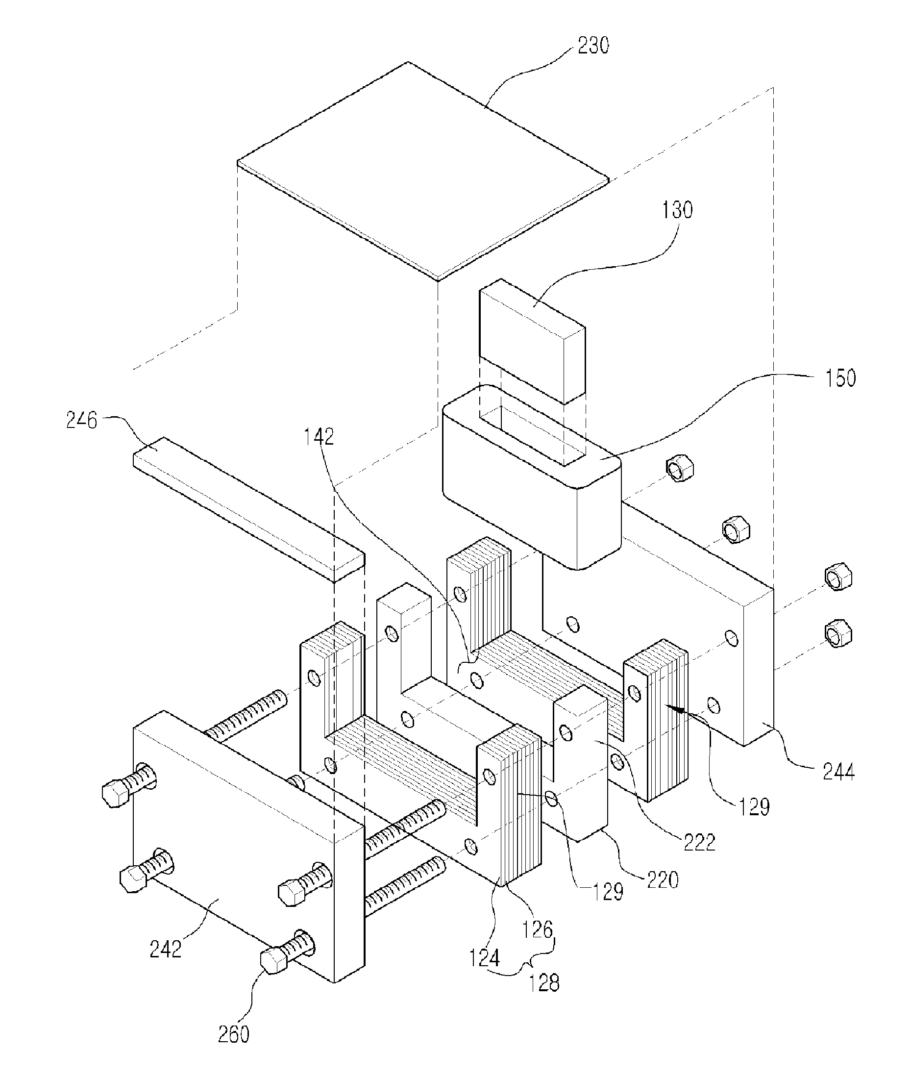
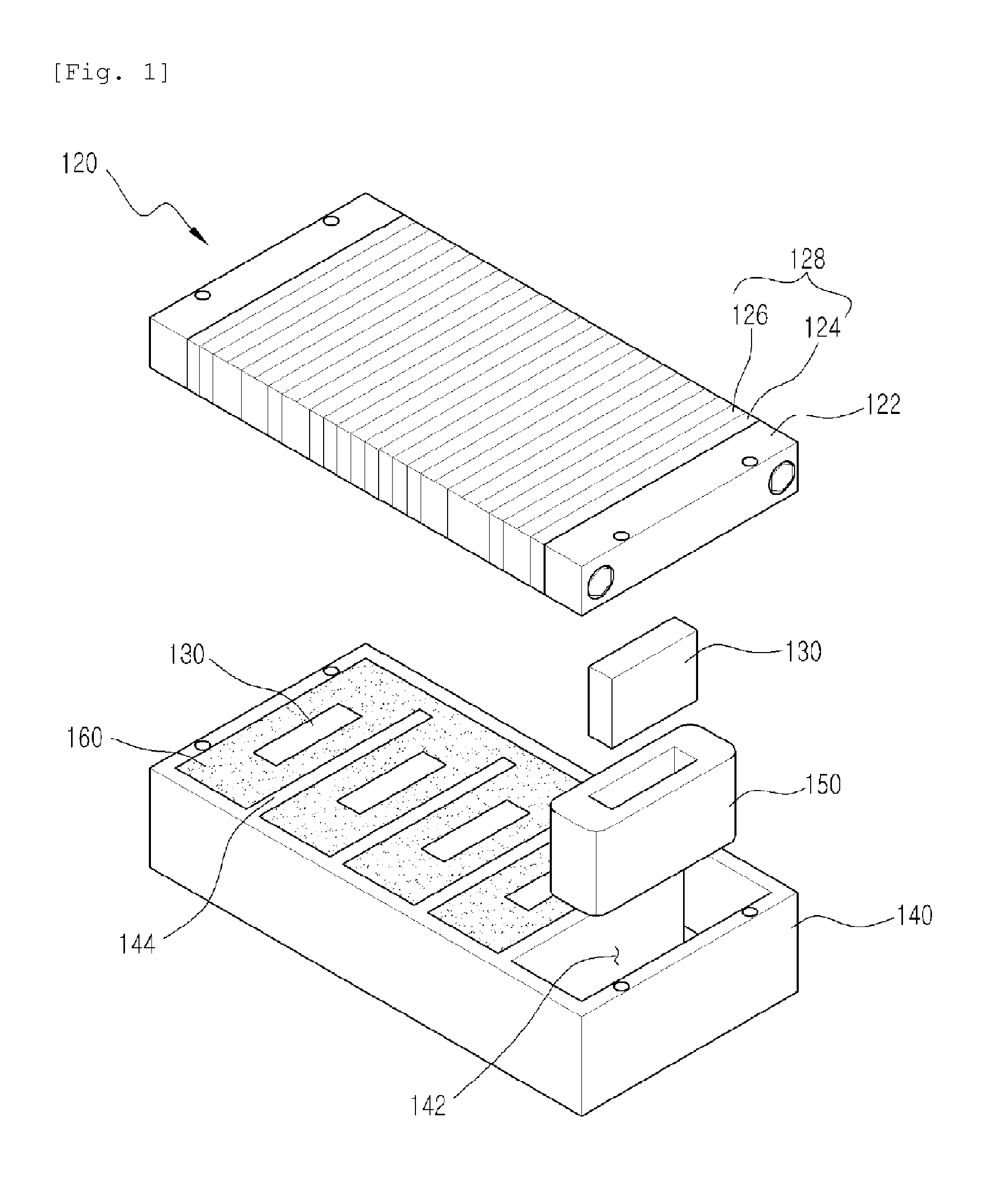
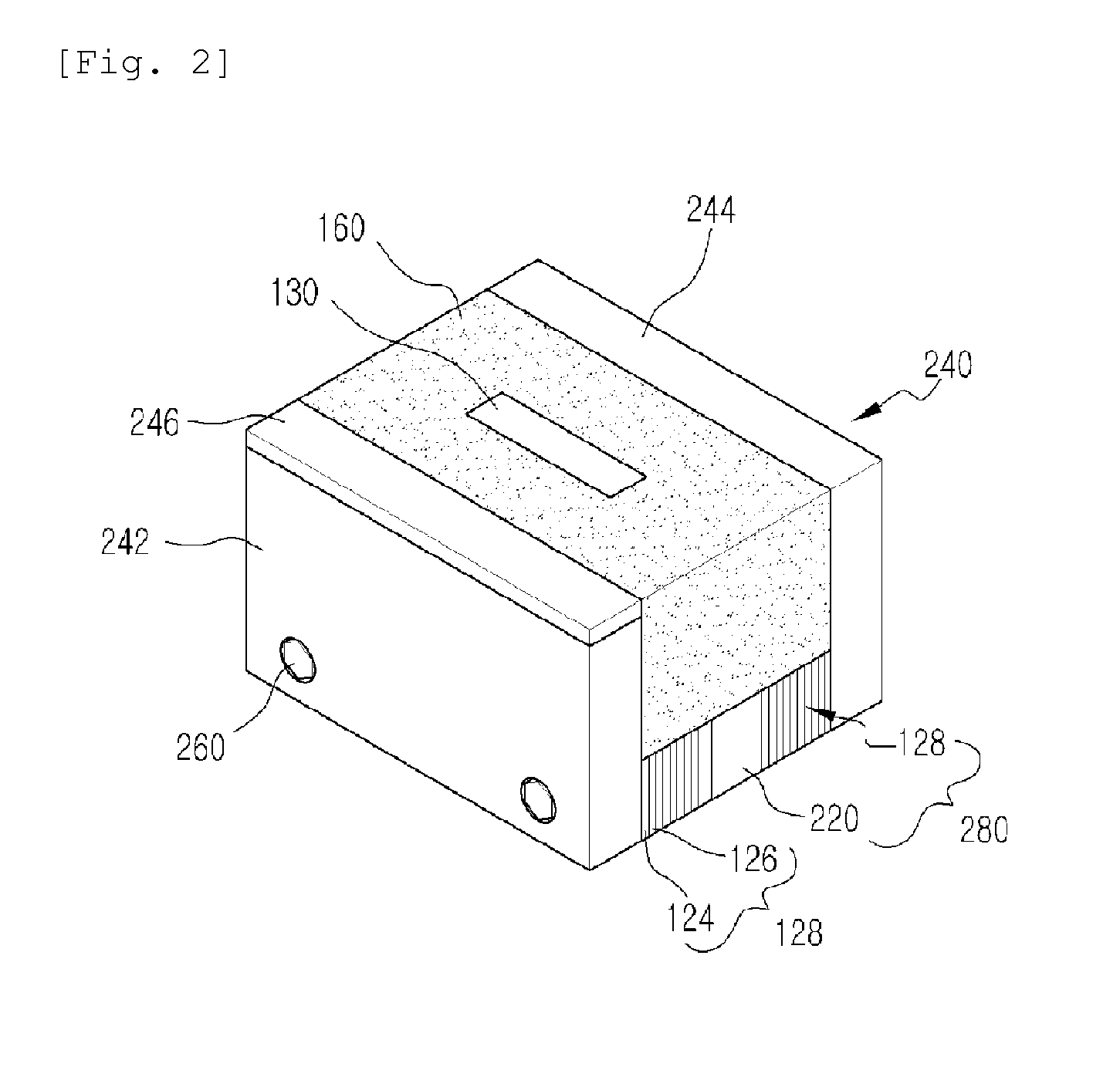
[0028]The present invention provides a magnetic chuck that can attach and process a workpiece by a magnetic force including: a magnetic substance having magnetism; a small-sized magnetic member including panel units each heating treating and provided at both sides of the magnet substance and in which a non-magnetic panel is inserted between a plurality of magnetic panels; a sidewall unit in which a first sidewall and a second sidewall are provided at both sides, respectively of the small-sized magnetic member to form a receiving groove; a coupling member that penetrates and couples the small-sized magnetic member and the sidewall unit; an Alnico magnet inserted into the receiving groove; a coil that encloses the Alnico magnet; a filling material that binds the Alnico magnet and the coil and that is filled in the receiving groove so that one side surface of the Alnico magnet may be exposed; and a first insulator that enables a magnetic force flowing to the first sidewall to flow to a...


PUM

PropertyMeasurementUnit
magnetic forceaaaaaaaaaa
magneticaaaaaaaaaa
non-magneticaaaaaaaaaa

Abstract

The present invention relates to a magnetic chuck. The present invention provides a magnetic chuck capable of attaching and processing a workpiece by magnetism, and the magnetic chuck comprises: a small-sized magnetic member which includes a magnetic substance having magnetic properties, and panel units that are respectively positioned on both sides of said magnetic substance through heat treatment and in which non-magnetic panels are inserted between a plurality of magnetic panels; a sidewall unit which has accommodation grooves by positioning respectively a first sidewall and a second sidewall on both sides of said small-sized magnetic member; coupling members which are coupled by penetrating said small-sized magnetic member and the sidewall unit; alnico magnets which are inserted into said accommodation grooves; coils which are inserted into said accommodation grooves, and enclose the alnico magnets; fillings which mutually couple said alnico magnets and said coils, and are filled in the accommodation grooves such that one side of the alnico magnets is exposed; and a first insulator which is equipped on one side of said first sidewall to allow magnetism, which flows into the first sidewall, to flow in another direction.

Description

CROSS-REFERENCE TO RELATED APPLICATION[0001]This application claims the benefit of Korean Patent Application No. 10-2011-0037438, filed on Apr. 21, 2011 in the Korean Intellectual Property Office, the disclosure of which is incorporated herein by reference.TECHNICAL FIELD[0002]The present invention relates to a magnetic chuck. More particularly, the present invention relates to a magnetic chuck that can perform a horizontal processing and a vertical processing by attaching a workpiece to a front surface of a magnetic chuck using in a machine tool and that can form one side corner of the magnetic chuck in an inclined surface inclined by a constant angle or that can process a workpiece in a predetermined angle by fixing a jig in which an inclined surface is formed.BACKGROUND ART[0003]In general, a chuck of a machine tool is an accessory device installed in a table of the machine tool to fix a workpiece and includes a common chuck, an air chuck, and a collet chuck, and there is a magne...

Claims


Application Information

Patent Timeline
Patent Type & Authority Applications(United States)
IPC IPC(8): H01F7/02
CPCH01F7/02B23Q3/1543H01F7/0252B23Q3/00B23Q3/15B25B11/00
Inventor LEE, YONG GOOLEE, JONG SUKLEE, JONG MIN
Owner JIN YOUNG PRECISION MACHINE
Why Eureka
Try Eureka