Vehicle with a low gravity center and aerial work platform

Active Publication Date: 2018-03-01
ZHEJIANG DINGLI MACHINERY CO LTD
View PDF2 Cites 1 Cited by
  • Summary
  • Abstract
  • Description
  • Claims
  • Application Information

AI Technical Summary

Benefits of technology

[0018]In present invention, as the power system, fuel tank, and hydraulic tank are all located at one side of the vehicle frame, and the total weight of these and other related components amounts to 1000 Kg-1500 Kg after injection of related materials, the gravity center of the aerial work platform is able to be lowered by 0.4 m-0.6 m, thus strongly improving off-road performance and grade-ability of the entire platform. Accordingly, the aerial work platform is able to run under various complex environments. In addition, the horizontal reach of the aerial work platform is also increased, and work range of the same is also extended.
[0019]Correspondingly, the power system is disposed in the first box, while the fuel tank and hydraulic tank is disposed in the second box. The first and second boxes are able to protect relevant components therein effectively, avoiding collision of these components with external objects and thereby avoiding damages to

Problems solved by technology

This restricts off-road ability and grade-ability of the aerial work platform.
In addition, this also restricts horizontal reach of the aerial work platform.
In other words, the horizontal reach of an operation platform is

Method used


Image

  • Vehicle with a low gravity center and aerial work platform
  • Vehicle with a low gravity center and aerial work platform
  • Vehicle with a low gravity center and aerial work platform

Examples


Embodiment Construction

[0038]The present invention will be further described below with reference to accompanied drawings and exemplary embodiments. Here, identical numerals represent the identical components. In addition, detailed description of prior art will be omitted if it is unnecessary for illustration of the features of the present invention.

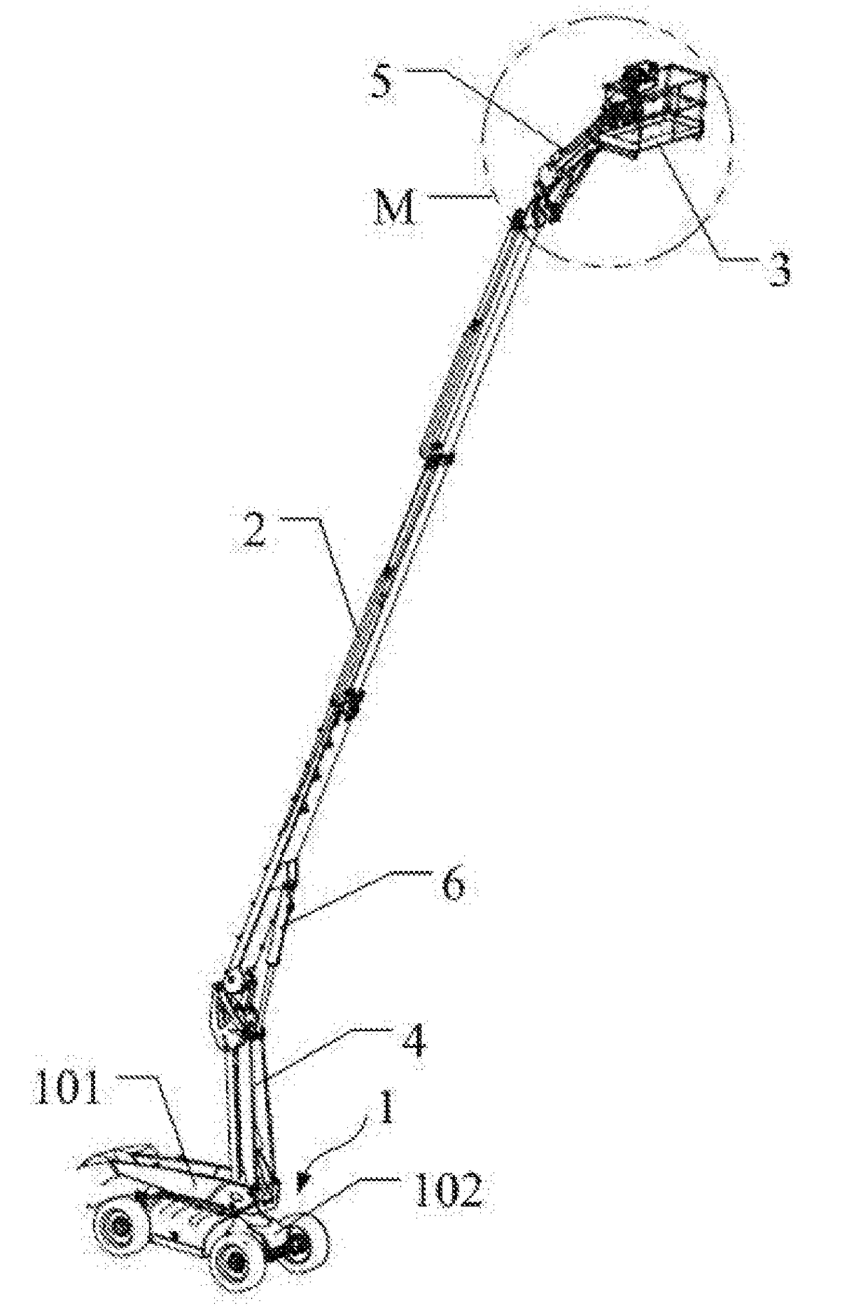
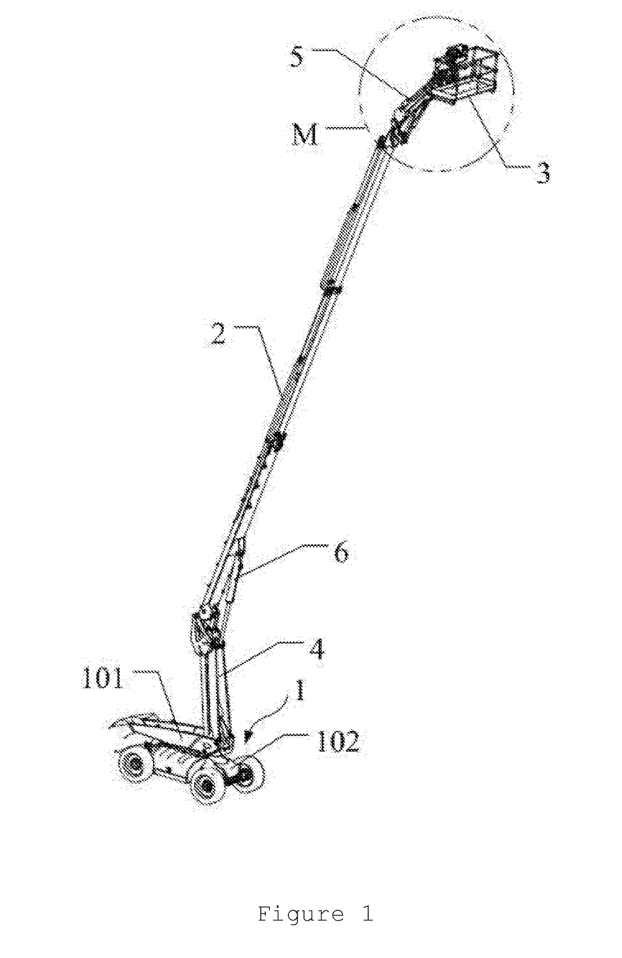
[0039]FIGS. 1-16 show a typical embodiment of an aerial work platform of the present invention. The aerial work platform includes a vehicle 1, a telescopic transmission component 2 pivotablly installed on the vehicle 1, and an operation platform 3 connected to a distal end of the telescopic transmission component 2 via a telescopic connection component 5.

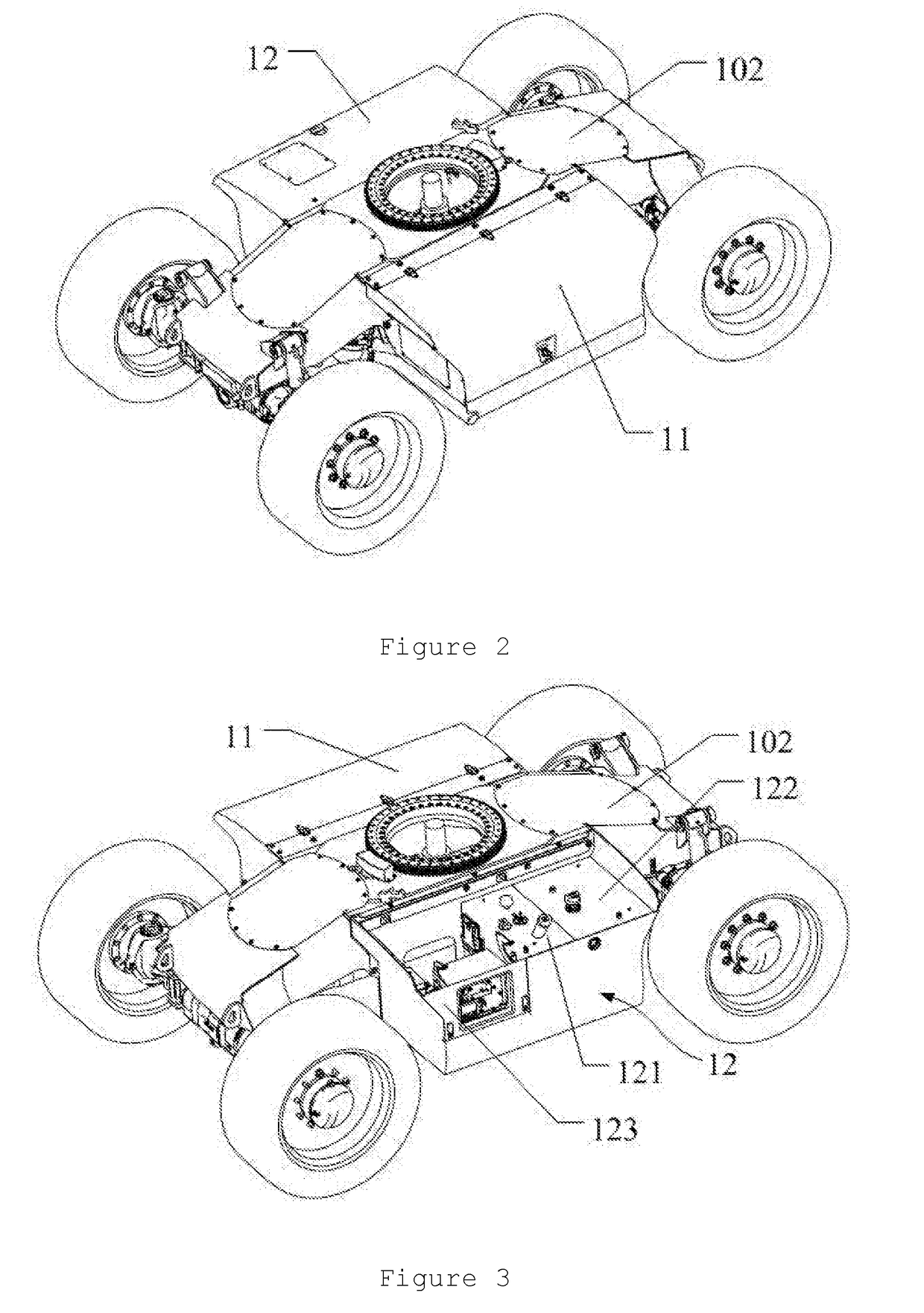
[0040]It is noted that the vehicle 1 includes a vehicle frame 102, a driving system, a fuel tank 121, and a hydraulic tank 122. The driving system includes a power system, a transmission mechanism, a control system, a driving mechanism, and a wheel assembly. The power system, fuel tank 121 and hydraulic tank 1...


PUM


Abstract

The present invention relates to the field of engineering mechanics and more particularly, relates to an engineering work vehicle, and most particularly, relates to a vehicle with a low gravity center and aerial work platform. The vehicle includes a vehicle frame, a power system, a fuel tank, and a hydraulic tank all of which are mounted at a side of the frame. Correspondingly, the embodiment of the invention also provides an aerial work platform which provides better off-road performance and grade-ability, can work in complicated environment, and owns a longer horizontal reach and larger working range. Moreover, maintenance and repair cost is decreased, lifetime is extended, integrity is higher and appearance looks better.

Description

CROSS REFERENCE TO RELATED APPLICATIONS[0001]The present application claims priority from Chinese Patent Application No. 201610778675.8 filed Aug. 31, 2016, all of which are hereby incorporated herein by reference.FIELD OF THE INVENTION[0002]The present invention relates to field of engineering mechanics and more particularly, relates to an engineering work vehicle, and most particularly, relates to a vehicle with a low gravity center and aerial work platform.BACKGROUND OF THE INVENTION[0003]Aerial work platform is an advanced aerial working mechanical device, and is capable of significantly improving efficiency, safety, and comfort of operators at height, and is also capable of reducing labor. Accordingly, it is widely employed in developed countries. This aerial work platform is also extensively used in China in many fields such as urban street lamp maintenance, tree trimming or the like. With rapid development of Chinese economy, aerial work platform is increasingly required in m...

Claims


Application Information

Patent Timeline
IPC IPC(8): B66F17/00B66F7/04B66F11/04B66F7/22A62B35/00
CPCB66F17/006B66F7/04B66F11/046B66F7/28A62B35/0075B66F13/00B66F7/22B66F11/04B66C23/705B66F9/07513B60K5/12B60K15/03B60K17/06
Inventor XU, SHUGEN
Owner ZHEJIANG DINGLI MACHINERY CO LTD
Why Eureka
Try Eureka