

Low energy photobioreactor system
a photobioreactor and low energy technology, applied in biomass after-treatment, biochemical apparatus and processes, specific use bioreactors/fermenters, etc., can solve the problem of low energy return on investment (eroi) of prior art systems, and achieve the effect of facilitating biomass growth
- Summary
- Abstract
- Description
- Claims
- Application Information
AI Technical Summary
Benefits of technology
Problems solved by technology
Method used
Image

Examples
Embodiment Construction
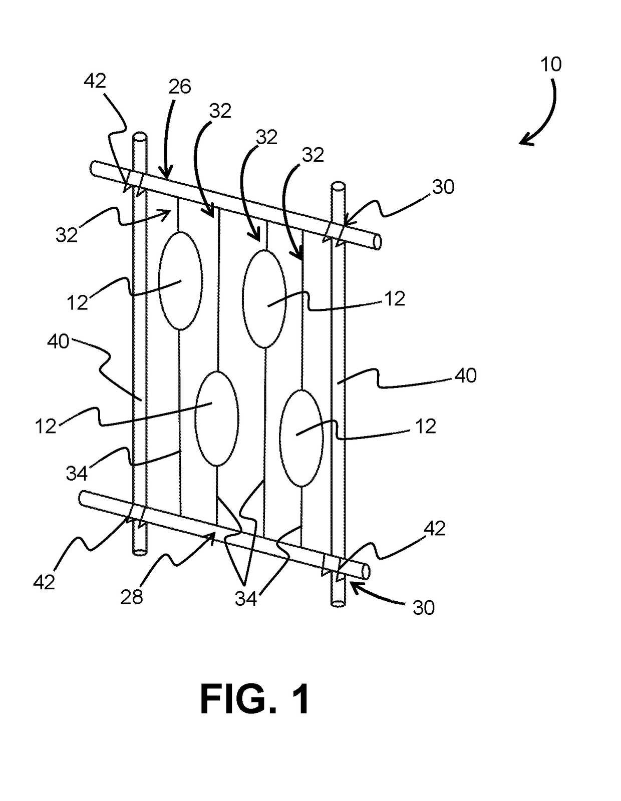
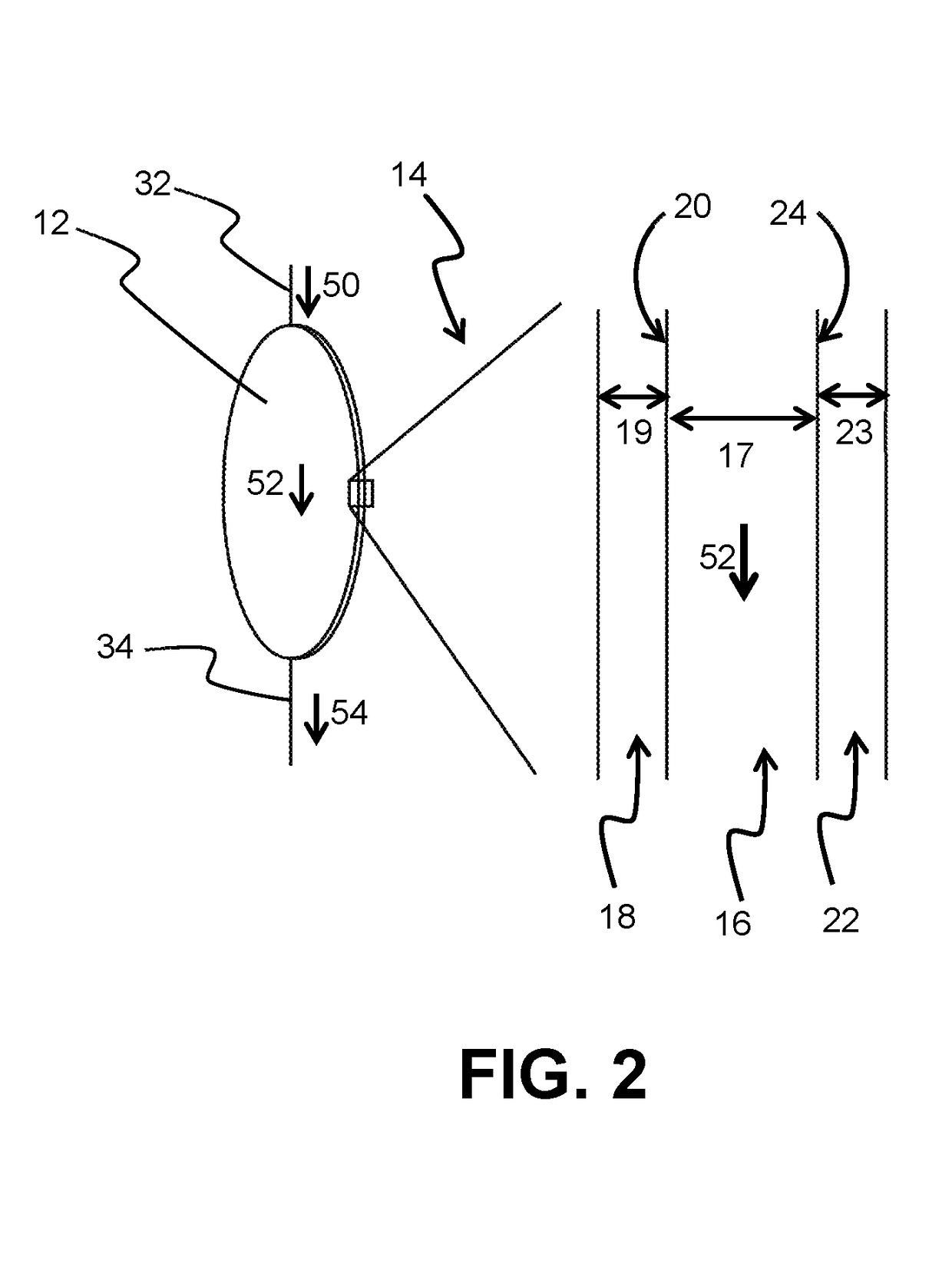
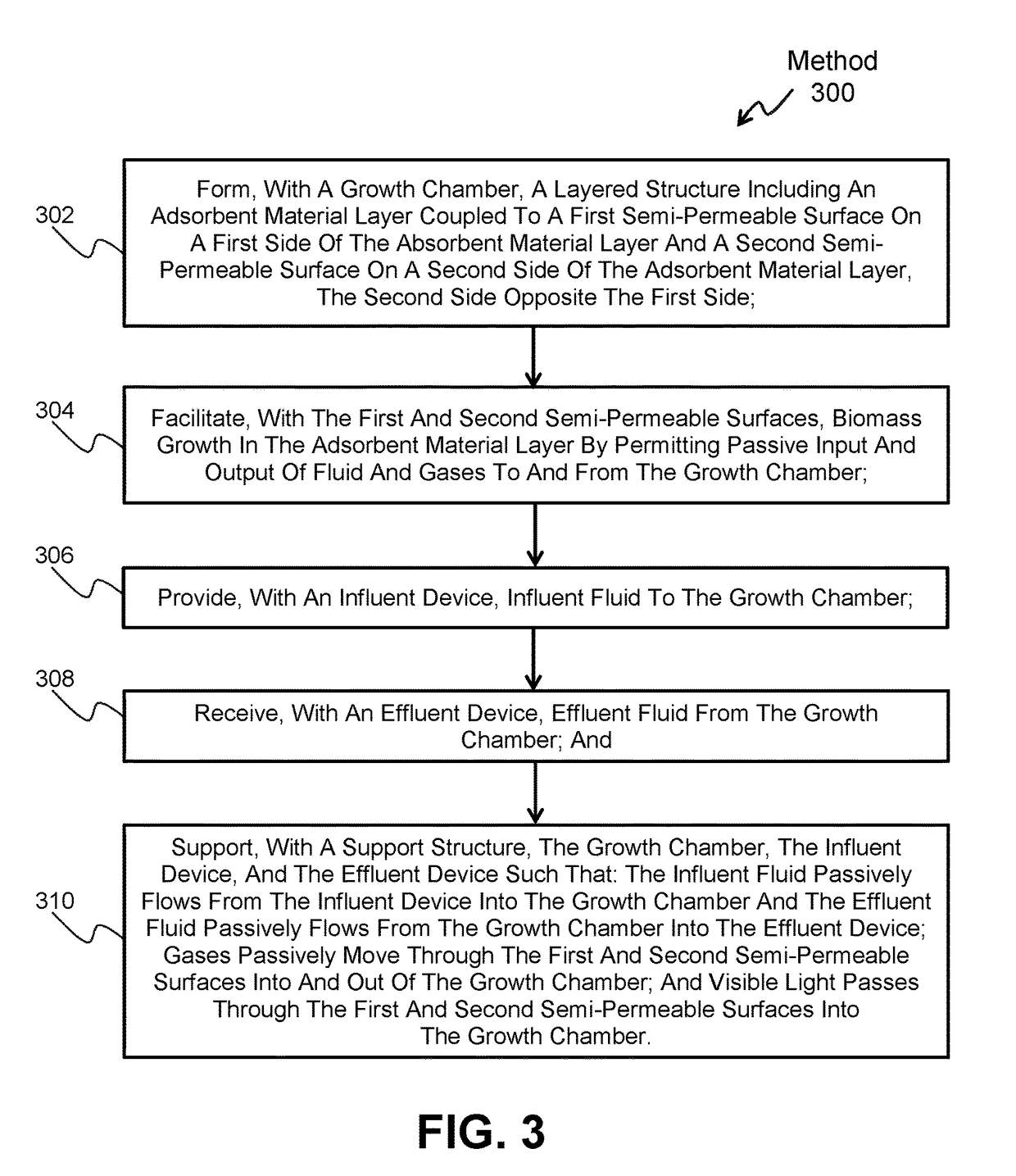
[0004]One aspect of the present disclosure relates to a photobioreactor system. The photobioreactor system comprises a growth chamber, an influent device, an effluent device, a support structure, and / or other components. The growth chamber may be configured to grow a biomass. The growth chamber may comprise a layered structure and / or other structures. The layered structure may include an adsorbent material layer coupled to a first semi-permeable surface on a first side of the adsorbent material layer and a second semi-permeable surface on a second side of the adsorbent material layer. The second side may be opposite the first side. The first and second semi-permeable surfaces may facilitate biomass growth in the adsorbent material layer by permitting passive input and output of fluid and gases to and from the growth chamber and / or other operations. The influent device may be configured to provide influent fluid to the growth chamber. The effluent device may be configured to receive ...
PUM
| Property | Measurement | Unit |
|---|---|---|
| thick | aaaaa | aaaaa |
| thick | aaaaa | aaaaa |
| thick | aaaaa | aaaaa |
Abstract
Description
Claims
Application Information