
Communication Networks, Relay Nodes for Communication Networks, and Methods of Transmitting Data Among a Plurality of Relay Nodes

a communication network and relay node technology, applied in the field of communication networks, can solve the problems of inability to use information, inability to install wires, economic and/or technical difficulties, etc., and achieve the effect of facilitating information utilization, facilitating information utilization, and facilitating data transmission

Pending Publication Date: 2018-03-01
ZHANG YIBING +2
View PDF36 Cites 44 Cited by
  • Summary
  • Abstract
  • Description
  • Claims
  • Application Information

AI Technical Summary

Benefits of technology

The patent text describes communication networks, relay nodes, and methods for transmitting data among them using non-dispersive guided acoustic waves. The technical effects include the ability to transmit data among multiple relay nodes using a single elongate tubular body, increased data transmission speed, and improved data transmission accuracy. The relay nodes include an electro-acoustic transmitter array and an electro-acoustic receiver, which induce non-dispersive guided acoustic waves within the tubular body. Overall, the patent text provides a solution for efficiently transmitting data in tubular bodies using advanced technology.

Problems solved by technology

Examples abound where the installation of wires is technically difficult and / or economically impractical.
The use of radio transmission also may be impractical, or unavailable, in cases where radio-activated blasting is occurring, and / or where the attenuation of radio waves near the elongate tubular body is significant.
However, this approach does not permit the information to be utilized during the drilling operation in which the information is obtained, and thus does not enable real-time utilization of the information.
However, placement of a physical cable along a drill pipe during drilling may be problematic.
As an example, the cable may become tangled and / or may break if secured along a rotating drill string.
However, even in this instance, the harsh downhole environment and the considerable force of the pipe as it scrapes across the surrounding borehole may damage the cable.
However, this can be difficult, as placement of wires along the casing string requires that thousands of feet of cable be carefully unspooled and fed during pipe connection and run-in.
In addition, if the wire runs outside of a casing string, it creates a potential weak spot in a cement sheath that surrounds the casing string.
This may contribute to a loss of pressure isolation between subsurface intervals.
Furthermore, it generally is not feasible to pass wires through a casing mandrel for subsea applications.
In sum, passing cable in the annulus adds significant challenges and cost, both for equipment and for rig time, to well completions.
A downside to mud pulse telemetry is that it transmits data to the surface at relatively slow rates, typically less than 20 bits per second (bps), and this data rate decreases even further as the length of the wellbore increases.
Slow data transmission rates can be costly to the drilling process.
Since many survey stations may be required, this downlink / uplink time can be very expensive, especially on deepwater rigs where daily operational rates can exceed $2 million.
Similarly, the time it takes to downlink instructions and uplink data associated with many other tasks, such as setting parameters in a rotary steerable directional drilling tool and / or obtaining a pressure reading from a pore-pressure-while-drilling tool, can be very costly.
Thus, there are economic and functional challenges to effective utilization of EM telemetry systems.
While high data transmission rates can be accomplished using RF signals in a downhole environment, the transmission range typically is limited to a few meters.

Method used


Image

  • Communication Networks, Relay Nodes for Communication Networks, and Methods of Transmitting Data Among a Plurality of Relay Nodes
  • Communication Networks, Relay Nodes for Communication Networks, and Methods of Transmitting Data Among a Plurality of Relay Nodes
  • Communication Networks, Relay Nodes for Communication Networks, and Methods of Transmitting Data Among a Plurality of Relay Nodes

Examples


Embodiment Construction

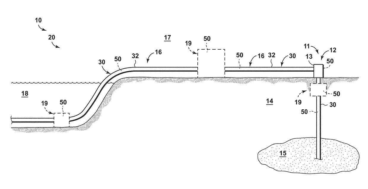
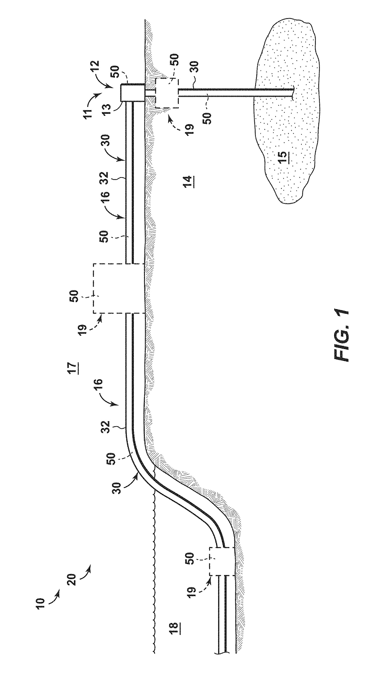
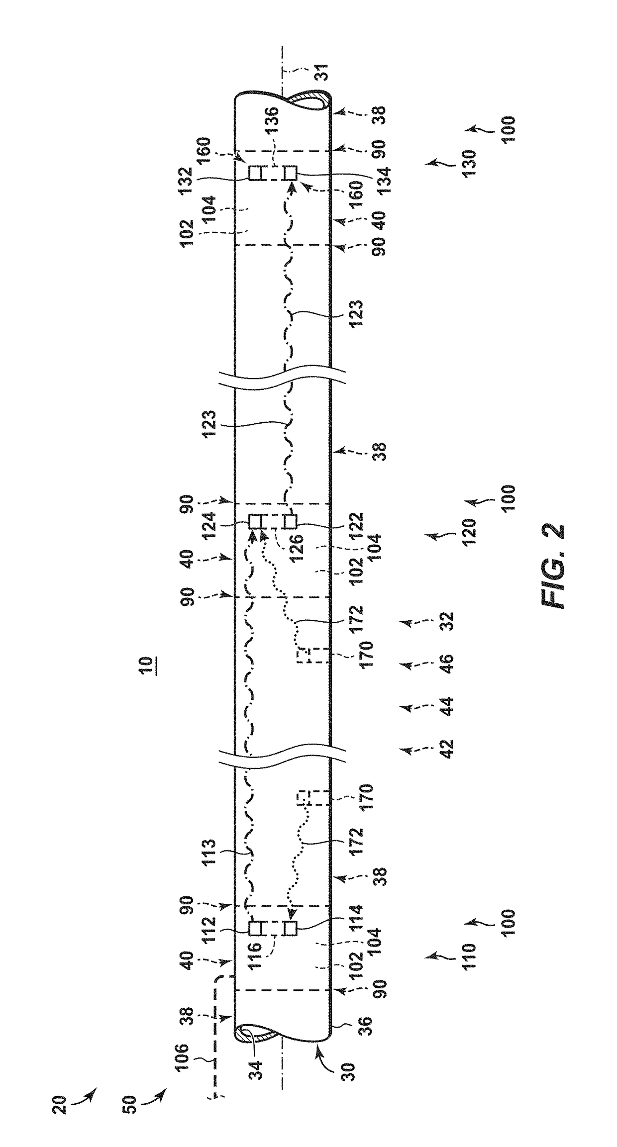
[0033]FIGS. 1-3 and 5-14 provide examples of communication networks 20, of wireless data transmission networks 50, of relay nodes 100 that may be included in communication networks 20 and / or in wireless data transmission networks 50, and / or of methods 200, according to the present disclosure. Elements that serve a similar, or at least substantially similar, purpose are labeled with like numbers in each of FIGS. 1-3 and 5-14, and these elements may not be discussed in detail herein with reference to each of FIGS. 1-3 and 5-14. Similarly, all elements may not be labeled in each of FIGS. 1-3 and 5-14, but reference numerals associated therewith may be utilized herein for consistency. Elements, components, and / or features that are discussed herein with reference to one or more of FIGS. 1-3 and 5-14 may be included in and / or utilized with any of FIGS. 1-3 and 5-14 without departing from the scope of the present disclosure. In general, elements that are likely to be included in a particul...


PUM


Abstract

Communication networks, relay nodes for communication networks, and methods of transmitting data among a plurality of relay nodes utilizing non-dispersive guided acoustic waves are disclosed herein. The communication networks include an elongate tubular body and a wireless data transmission network including a plurality of relay nodes. The relay nodes include an electro-acoustic transmitter array and an electro-acoustic receiver. The methods include inducing a first acoustic wave within the elongate tubular body with a first relay node, conveying the first acoustic wave along the elongate tubular body to a second relay node, and receiving the first acoustic wave with the second relay node. The methods further include inducing a second acoustic wave within the elongate tubular body with the second relay node, conveying the second acoustic wave along the elongate tubular body to a third relay node, and receiving the second acoustic wave with the third relay node.

Description

CROSS REFERENCE TO RELATED APPLICATIONS[0001]This application claims the benefit of U.S. Provisional Application Ser. No. 62 / 381,330 filed Aug. 30, 2016, entitled “Communication Networks, Relay Nodes for Communication Networks, and Methods of Transmitting Data Among a Plurality of Relay Nodes,” U.S. Provisional Application Ser. No. 62 / 381,335, filed Aug. 30, 2016 entitled “Zonal Isolation Devices Including Sensing and Wireless Telemetry and Methods of Utilizing the Same,” U.S. Provisional Application Ser. No. 62 / 428,367, filed Nov. 30, 2016, entitled “Dual Transducer Communications Node for Downhole Acoustic Wireless Networks and Method Employing Same,” U.S. Provisional Application Ser. No. 62 / 428,374, filed Nov. 30, 2016, entitled “Hybrid Downhole Acoustic Wireless Network,” U.S. Provisional Application Ser. No. 62 / 428,385, filed Nov. 30, 2016 entitled “Methods of Acoustically Communicating And Wells That Utilize The Methods,” U.S. Provisional Application Ser. No. 62 / 433,491, filed...

Claims


Application Information

Patent Timeline
IPC IPC(8): E21B47/16H04B11/00
CPCH04B11/00E21B47/16Y02D30/70E21B47/017E21B47/005E21B47/007E21B41/0085E21B47/18
Inventor ZHANG, YIBINGSONG, LIMINDISKO, MARK M.
Owner ZHANG YIBING
Learn More