Encoder and apparatus having the same

Active Publication Date: 2018-03-01
CANON PRECISION
View PDF0 Cites 4 Cited by
  • Summary
  • Abstract
  • Description
  • Claims
  • Application Information

AI Technical Summary

Benefits of technology

The present invention is about an encoder that can accurately calculate the difference in position between two objects or parts during a certain time period. This means that even if the calculation takes a long time, the encoder can still provide accurate results.

Problems solved by technology

The absolute type encoder needs to read more periodic patterns than the incremental type encoder, and requires a plurality of detectors corresponding to the number of periodic patterns, causing a more complicated structure.
However, even this encoder also has the following problems: Just after the detecting period of the detector in the sensor is switched, it takes a time for a periodic signal (analogue signal) output from the element in the detector, such as a light receiving element and a magnetic detecting element, to become stable.
Thus, a positional detection delays for each switch of the detecting period.
However, the encoder disclosed in Japanese Patent Laid-Open No. 2013-88191 may cause a relative position to shift where a calculating time period for the relative position with a plurality of signals having a changing period corresponding to a periodic pattern is longer than a predetermined time period.

Method used


Image

  • Encoder and apparatus having the same
  • Encoder and apparatus having the same
  • Encoder and apparatus having the same

Examples


first embodiment

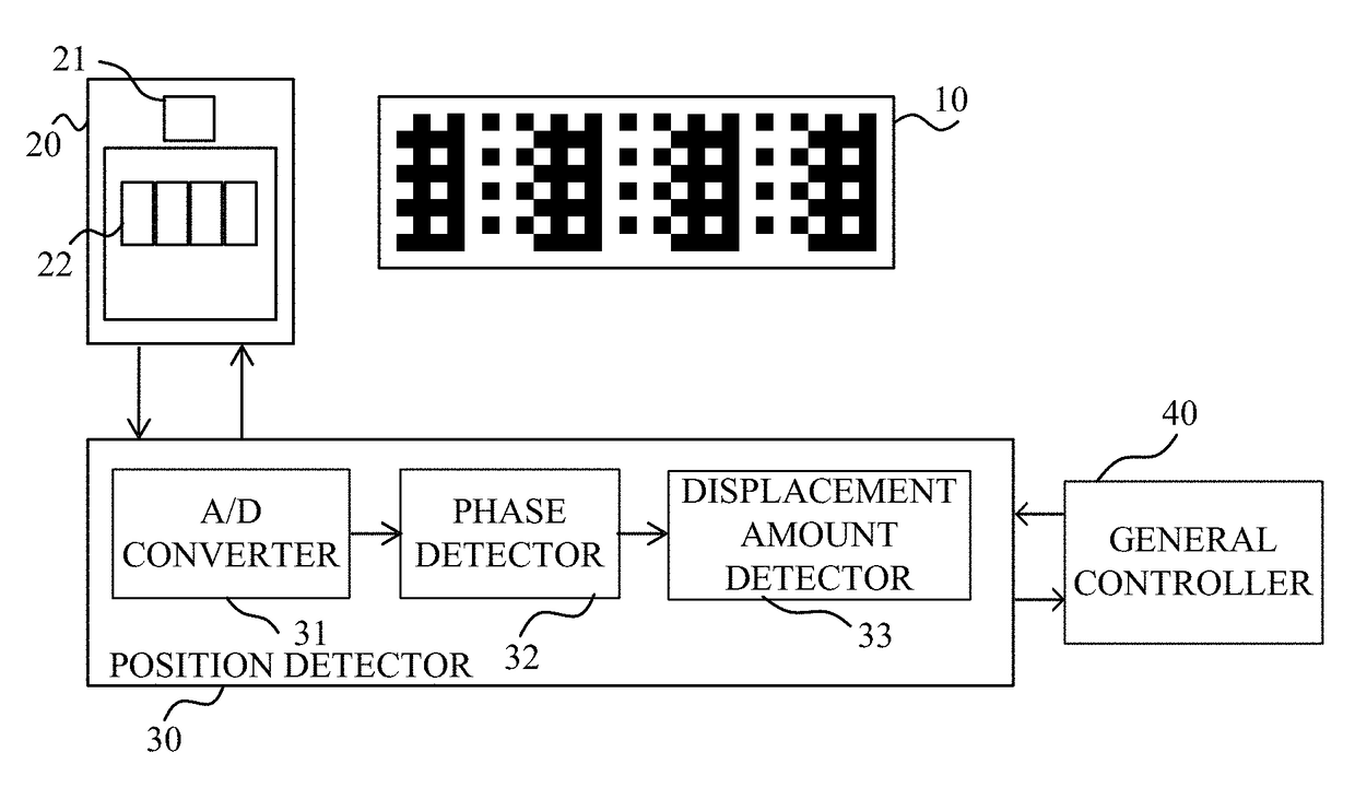
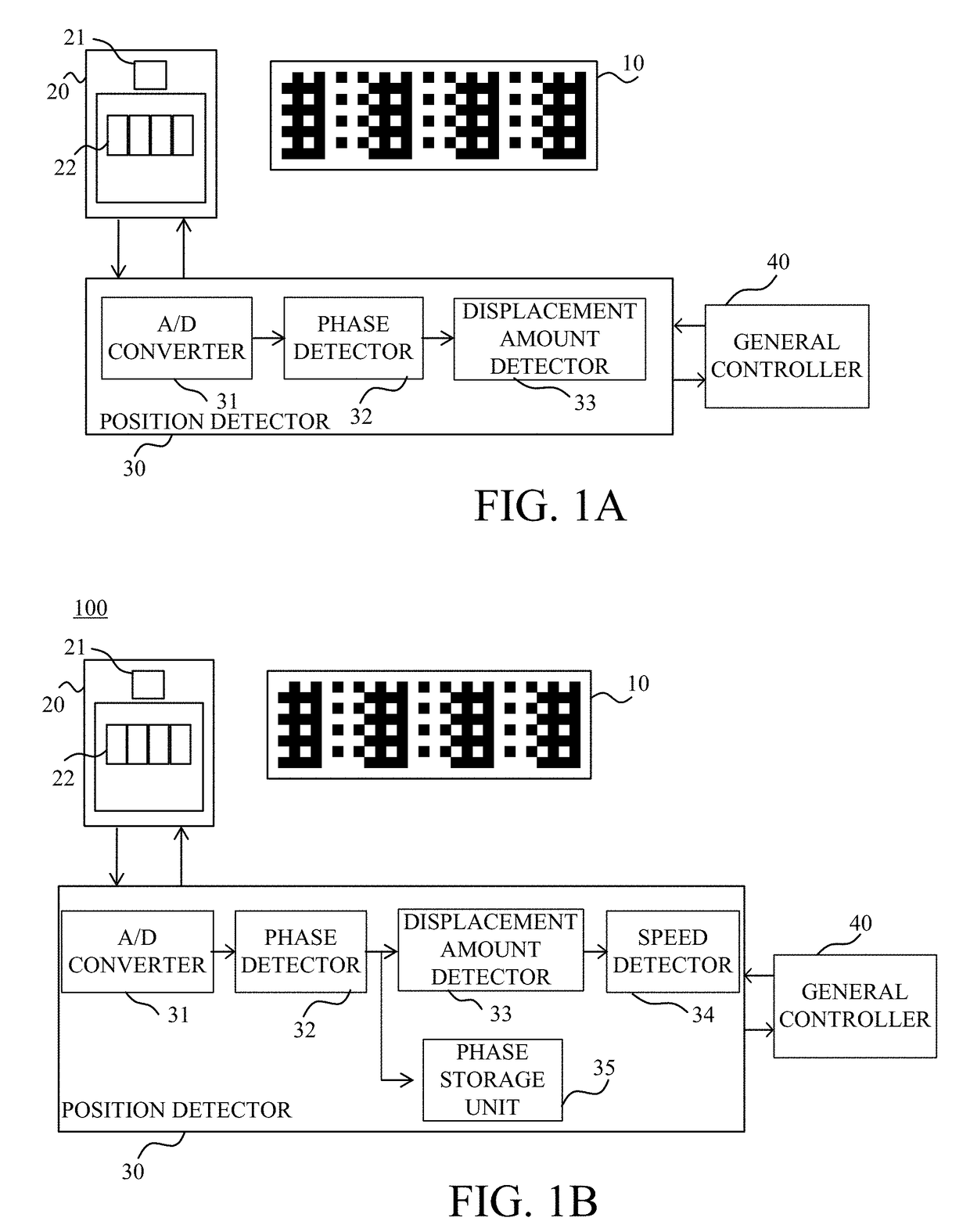
[0022]FIG. 1A is a block diagram illustrating a configuration of an encoder 100 according to this embodiment. The encoder 100 includes a scale 10, a sensor (detector) 20, a position detector (processor) 30, and a general controller 40. The encoder 100 is an optical reflection type absolute encoder that detects a position (relative position) of one of the scale 10 and the sensor 20 to the other of the scale 10 and the sensor 20.

[0023]In this embodiment, in an apparatus mounted with this encoder, the scale 10 is attached to an unillustrated movable member as an object of the relative position to be detected, and the sensor 20 is attached to a fixed or immovable member. Alternatively, the sensor 20 may be attached to the movable member and the scale 10 may be attached to the fixed member, and the relative position of the movable member relative to the fixed member may be detected. While this embodiment discusses a linear type encoder, a rotary type encoder may be configured similar to ...

second embodiment

[0068]This embodiment discusses the second process different from that in the first embodiment. The first embodiment initializes the displacement amount detector 33 before the relative position is calculated, but this embodiment stores the relative displacement amount when the displacement amount detector 33 starts calculating the relative position. The first process in this embodiment is similar to that in the first embodiment and a description thereof will be omitted. This embodiment discusses only the second process.

[0069]FIG. 9 is a flowchart of the second process according to this embodiment. FIG. 10 illustrates an operational sequence of the general controller 40 according to this embodiment.

[0070]Since the steps S2001 to S2003 are the same as the steps S201 to S203 in FIG. 6, a description thereof will be omitted.

[0071]In the step S2004, the displacement amount detector 33 stores a relative displacement amount when a calculation of the first relative position starts.

[0072]In ...

third embodiment

[0076]FIG. 11 is a block diagram illustrating a configuration of an imaging apparatus (optical apparatus), such as a digital camera and a video camera, as one illustrative apparatus equipped with the encoder described in the first and second embodiments. In this imaging apparatus, the encoder is used to detect an absolute position of a movable lens in a lens barrel.

[0077]In FIG. 11, the encoder includes the scale 10, the sensor 20, the position detector 30, and the general controller 40. The scale 10 is attached to an inner circumference surface of a cam ring 50 having a cylindrical shape that rotates around the optical axis in the lens barrel. The cam ring 50 is rotated by an unillustrated actuator.

[0078]An imaging optical system 51 is housed in the lens barrel. The imaging optical system 51 includes a movable lens 52 (such as a magnification varying lens and a focus lens) that is movable in the optical axis direction by a cam formed the cam ring 50, as the cam ring 50 is rotated.

[...


PUM


Abstract

An encoder includes a scale, a detector, and a processor. The processor executes a second process while executing a first process, calculates a first relative position of one of the scale and the detector to the other of the scale and the detector when a calculation of a relative position between them starts, and then calculates a second relative position of the one to the other based on a relative displacement amount between them and the first relative position.

Description

BACKGROUND OF THE INVENTIONField of the Invention[0001]The present invention relates to an encoder used for a variety of apparatuses, such as an optical apparatus, and configured to output a signal indicative of a position along with a relative movement between a scale and a sensor as a movable member moves in the apparatus.Description of the Related Art[0002]An encoder used to detect a position and a speed of a movable member includes a scale having a periodic pattern, and a sensor having a detector that outputs a periodic signal that periodically changes according to the periodic pattern with the relative movement to the scale. One encoder is an incremental type encoder that generates two periodic signals that has phases different from each other (a pair or set of two-phase or biphase signals) based on one periodic pattern, and detects a relative displacement between the scale and the sensor based on the number of periods and the phases in the two-phase signals. An absolute type e...

Claims


Application Information

Patent Timeline
IPC IPC(8): G01D5/347G01D5/245
CPCG01D5/34715H03M1/001G01D5/2454G01D5/34776G01D5/34792
Inventor KUDO, KOUSUKENAKAMURA, HITOSHI
Owner CANON PRECISION
Why Eureka
Try Eureka