Post-critical reflection muting in seismic migration

a post-critical and seismic migration technology, applied in the field of post-critical reflection muting in seismic migration, can solve the problems of complex set of alternating artifacts in seismic images, and complex set of pre-critical and post-critical regions, so as to reduce the scope of claimed subject matter, improve data processing efficiency, efficiency and accuracy

Active Publication Date: 2018-03-01
SCHLUMBERGER TECH CORP
View PDF6 Cites 4 Cited by
  • Summary
  • Abstract
  • Description
  • Claims
  • Application Information

AI Technical Summary

Benefits of technology

[0016]Thus, the computing systems and methods disclosed herein are more effective methods for processing collected data that may, for example, correspond to a surface and a subsurface region. These computing systems and methods increase data processing effectiveness, efficiency, and accuracy. Such methods and computing systems may complement or replace conventional methods for processing collected data. This summary is provided to introduce a selection of concepts that are further described below in the detailed description. This summary is not intended to identify key or essential features of the claimed subject matter, nor is it intended to be used as an aid in limiting the scope of the claimed subject matter.

Problems solved by technology

Energy from waves impinging on the interface at angles greater than or equal to the critical angle can cause artifacts in the seismic image.
Since the critical angle is smaller for high-contrast interfaces, this post-critical energy commonly causes artifacts at salt or carbonate boundaries or the sea-floor, for example.
However, since the normal to the interface and direction of incoming waves can change rapidly, particularly for rugose interfaces, there is often a complex set of alternating pre-critical and post-critical regions.

Method used


Image

  • Post-critical reflection muting in seismic migration
  • Post-critical reflection muting in seismic migration
  • Post-critical reflection muting in seismic migration

Examples


Embodiment Construction

[0027]Reference will now be made in detail to embodiments, examples of which are illustrated in the accompanying drawings and figures. In the following detailed description, numerous specific details are set forth in order to provide a thorough understanding of the invention. However, it will be apparent to one of ordinary skill in the art that the invention may be practiced without these specific details. In other instances, well-known methods, procedures, components, circuits and networks have not been described in detail so as not to unnecessarily obscure aspects of the embodiments.

[0028]It will also be understood that, although the terms first, second, etc. may be used herein to describe various elements, these elements should not be limited by these terms. These terms are only used to distinguish one element from another. For example, a first object could be termed a second object, and, similarly, a second object could be termed a first object, without departing from the scope ...


PUM


Abstract

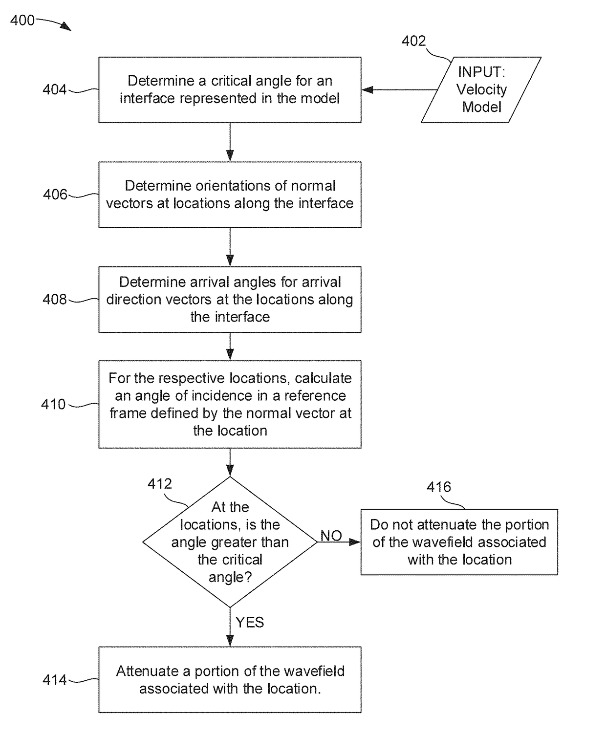
A method for processing seismic data includes obtaining a velocity model, determining a critical angle for an interface represented in the velocity model based on a ratio between velocity of the seismic wave on first and second sides of the interface, determining an orientation of a normal vector extending normal to a location of the interface, determining an orientation of an arrival direction vector of a wavefield at the location of the interface, calculating an angle between the normal vector and the arrival direction vector, determining that the angle between the normal vector and the arrival direction vector is greater than the critical angle at the location, and attenuating the wavefield associated with the location in response to determining that the angle between the normal vector and the arrival direction vector is greater than the critical angle at the location.

Description

BACKGROUND[0001]Seismic imaging through migration depends in part on modelling the behavior of seismic waves. The subterranean domain being imaged generally includes interfaces wherein the velocity of the seismic wave propagation changes. At such an interface with a velocity change, wave behavior depends on the incident angle. When the incident angle is less than the critical angle, part of the energy is reflected and part transmitted. At the critical angle, the transmitted wave travels parallel or along the interface. Beyond the critical angle, the energy is reflected.[0002]Energy from waves impinging on the interface at angles greater than or equal to the critical angle can cause artifacts in the seismic image. Since the critical angle is smaller for high-contrast interfaces, this post-critical energy commonly causes artifacts at salt or carbonate boundaries or the sea-floor, for example. However, since the normal to the interface and direction of incoming waves can change rapidly...

Claims


Application Information

Patent Timeline
Patent Type & Authority Applications(United States)
IPC IPC(8): G01V1/36G01V1/28
CPCG01V1/36G01V2210/67G01V1/282G01V2210/51G01V1/28
Inventor COATES, RICHARDLAPILLI, CINTIAFLATH, HANNAHKULAKOV, DMITRY
Owner SCHLUMBERGER TECH CORP
Why Eureka
Try Eureka