
Distributed sensor network for measuring and optimizing wireless networks

a distributed sensor network and wireless network technology, applied in the field of planning, validation and optimization of large-scale local area wireless network infrastructure, can solve the problems of inaccurate measurement of signal quality and laborious process of large-scale wireless network

Active Publication Date: 2018-03-01
FOCUS STRATEGIES CAPITAL ADVISORS LLC +1
View PDF6 Cites 17 Cited by
  • Summary
  • Abstract
  • Description
  • Claims
  • Application Information

AI Technical Summary

Benefits of technology

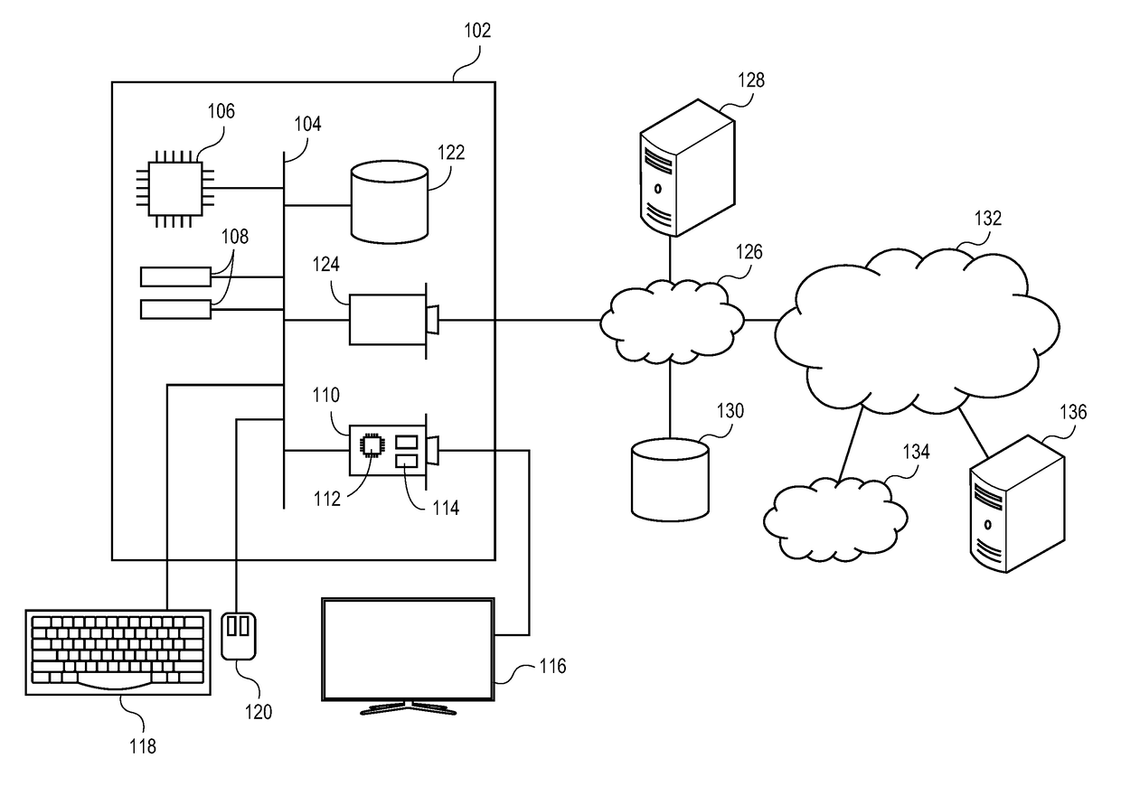
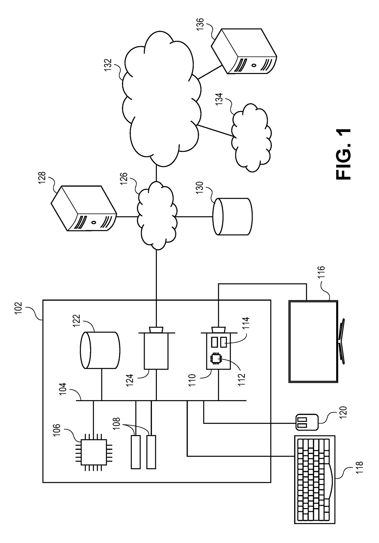
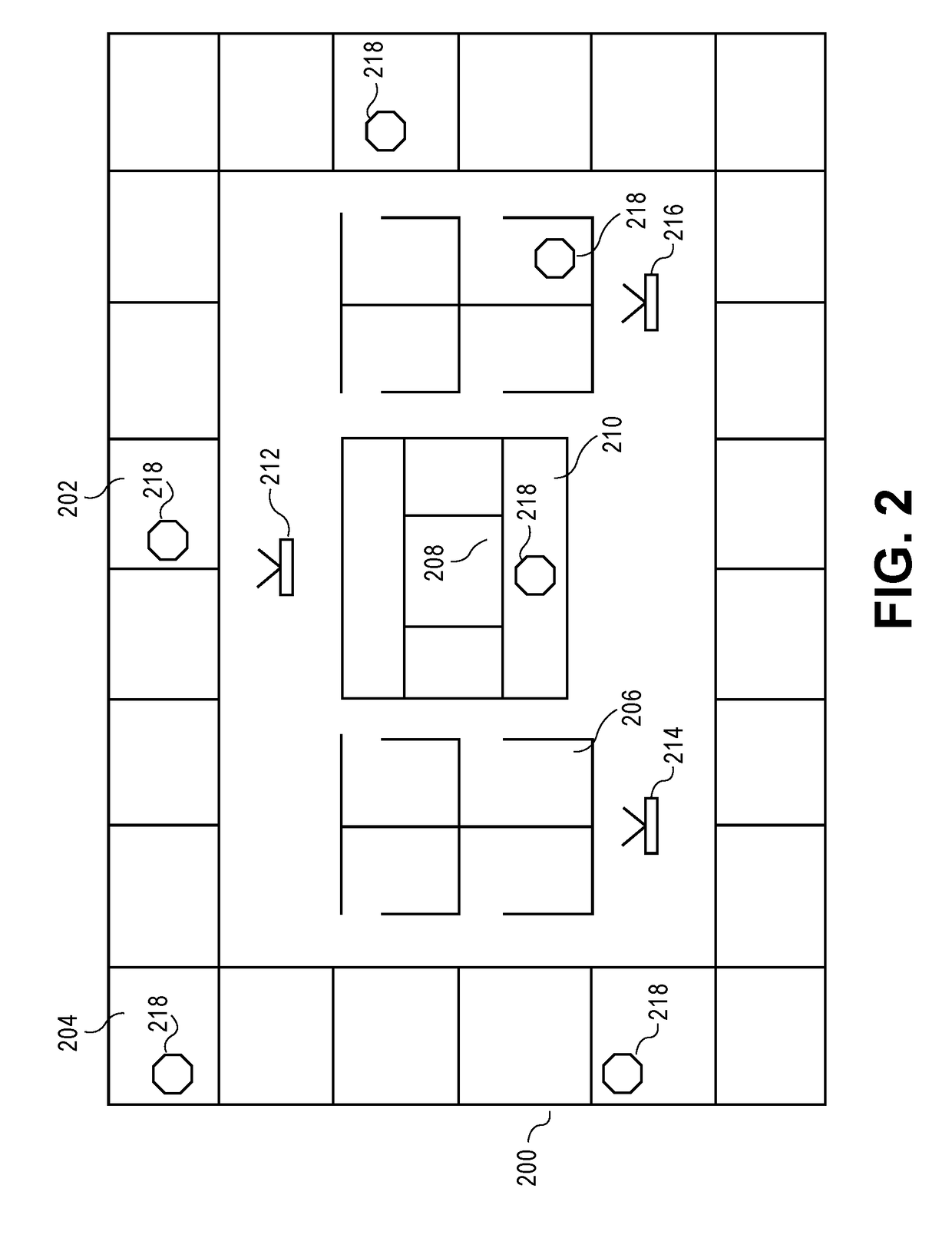
This patent describes an apparatus for determining placements for multiple access points in a wireless network. It uses a processor and sensors to create a floor plan and determine the initial placement of the access points based on signal quality. It then creates placements for sensors that communicate with the access points, simulates coverage maps for different placements, and selects the best placement for the access points based on the signal quality. The apparatus makes it easy for users to set up the wireless network and ensures optimal coverage.

Problems solved by technology

Traditionally, determining optimal placements of access points for large-scale wireless networks has been a laborious process, requiring deploying the access points in a proposed configuration, measuring signal quality at a variety of locations, moving the access points to adjust coverage, and repeating until adequate coverage is achieved throughout the deployment site.
In addition to the required labor, this process is slow and results in an adequate configuration, rather than an optimal one.
However, techniques for simulating signal quality across a wide variety of configurations without actually deploying the access points and measuring the signal quality provide inaccurate results due to variable signal propagation from real world effects such as interfering networks, different building materials, furniture, etc.

Method used


Image

  • Distributed sensor network for measuring and optimizing wireless networks
  • Distributed sensor network for measuring and optimizing wireless networks
  • Distributed sensor network for measuring and optimizing wireless networks

Examples


Embodiment Construction

[0015]At a high level, embodiments of the disclosure initially measure network signal coverage using wireless network sensors placed throughout a deployment site. The measurements from these sensors can then be fed, together with a floor plan for the deployment site, into a simulation engine that can estimate the optimal deployment for access points using (for example) Monte Carlo simulation. This simulation engine can then recommend optimal access point placements and channel assignments to maximize signal coverage across the deployment site.

[0016]The subject matter of embodiments of the disclosure is described in detail below to meet statutory requirements; however, the description itself is not intended to limit the scope of claims. Rather, the claimed subject matter might be embodied in other ways to include different operations or combinations of operations similar to the ones described in this document, in conjunction with other present or future technologies. Minor variations...


PUM


Abstract

Methods of planning network provisioning that incorporate real-world measurements of signal quality into simulations of signal quality under alternative configurations. In one embodiment, the disclosure includes a method of determining placements for access points in a wireless network, comprising ingesting a floor plan for a deployment site, determining initial placements for the access points, determining placements for sensors, each sensor configured to wirelessly communicate with at least one access point, measuring a signal metric for each sensor, based at least in part on the measured signal metric for each of the sensors, simulating a projected coverage map for a plurality of alternate placements for the access points, determining an placement of the access points, and presenting, to a user, the placement of the plurality of access points.

Description

RELATED APPLICATIONS[0001]This non-provisional patent application claims priority benefit, with regard to all common subject matter, of earlier-filed U.S. Provisional Patent Application No. 62 / 380,909 filed Aug. 29, 2017 and entitled DISTRIBUTED SENSOR NETWORK FOR MEASURING AND OPTIMIZING WIRELESS NETWORKS. The identified earlier-filed provisional patent application is hereby incorporated by reference in its entirety into the present application. This non-provisional patent application also shares certain common subject matter with earlier-filed U.S. patent application Ser. No. 14 / 506,106 filed Oct. 3, 2014 and entitled PLACED WIRELESS INSTRUMENTS FOR PREDICTING QUALITY OF SERVICE and with earlier-filed U.S. patent application Ser. No. 15 / 048,801 filed May 19, 2016 and entitled SYSTEM AND METHOD FOR GENERATING A GRAPHIC ILLUSTRATION OF WIRELESS NETWORK PERFORMANCE. These identified earlier-filed patent applications are hereby incorporated by reference in their entirety into the pres...

Claims


Application Information

Patent Timeline
Patent Type & Authority Applications(United States)
IPC IPC(8): G06F17/50G01D15/06
CPCG01D15/06G06F17/5072H04W16/18H04W24/02H04W24/06H04W24/08G06F30/392
Inventor KASCH, WILLIAM THOMAS MORGANBARMETTLER, MARK G.
Owner FOCUS STRATEGIES CAPITAL ADVISORS LLC
Learn More