Resin filling method and resin filling device for magnet embedded core

Active Publication Date: 2018-03-01
KURODA PRECISION INDS
View PDF1 Cites 4 Cited by
  • Summary
  • Abstract
  • Description
  • Claims
  • Application Information

AI Technical Summary

Benefits of technology

[0017]As described above, according to the present invention, it is possible to fix the permanent magnet in the magnet insertion hole accurately b

Problems solved by technology

However, in the configuration of the aforementioned conventional technology, there is a problem that a burr (resin residue at the gate) protruding more outward than the axial end surface of the laminated iron core (motor core) is formed

Method used


Image

  • Resin filling method and resin filling device for magnet embedded core
  • Resin filling method and resin filling device for magnet embedded core
  • Resin filling method and resin filling device for magnet embedded core

Examples


Example

[0028]Embodiments of the present invention are described in the following with reference to the appended drawings.

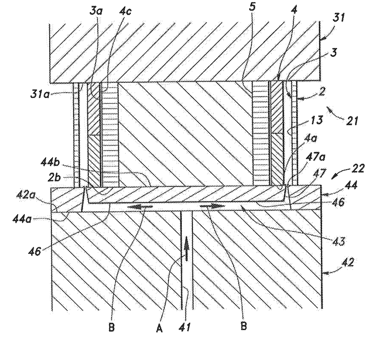
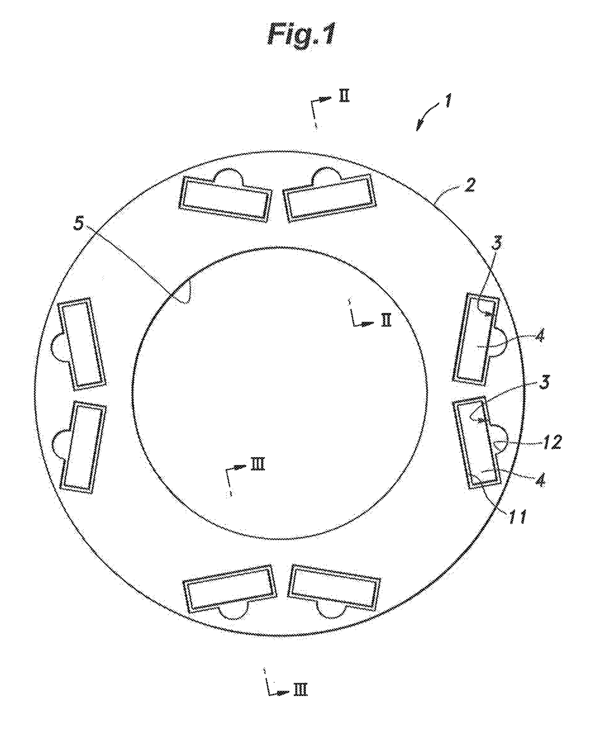
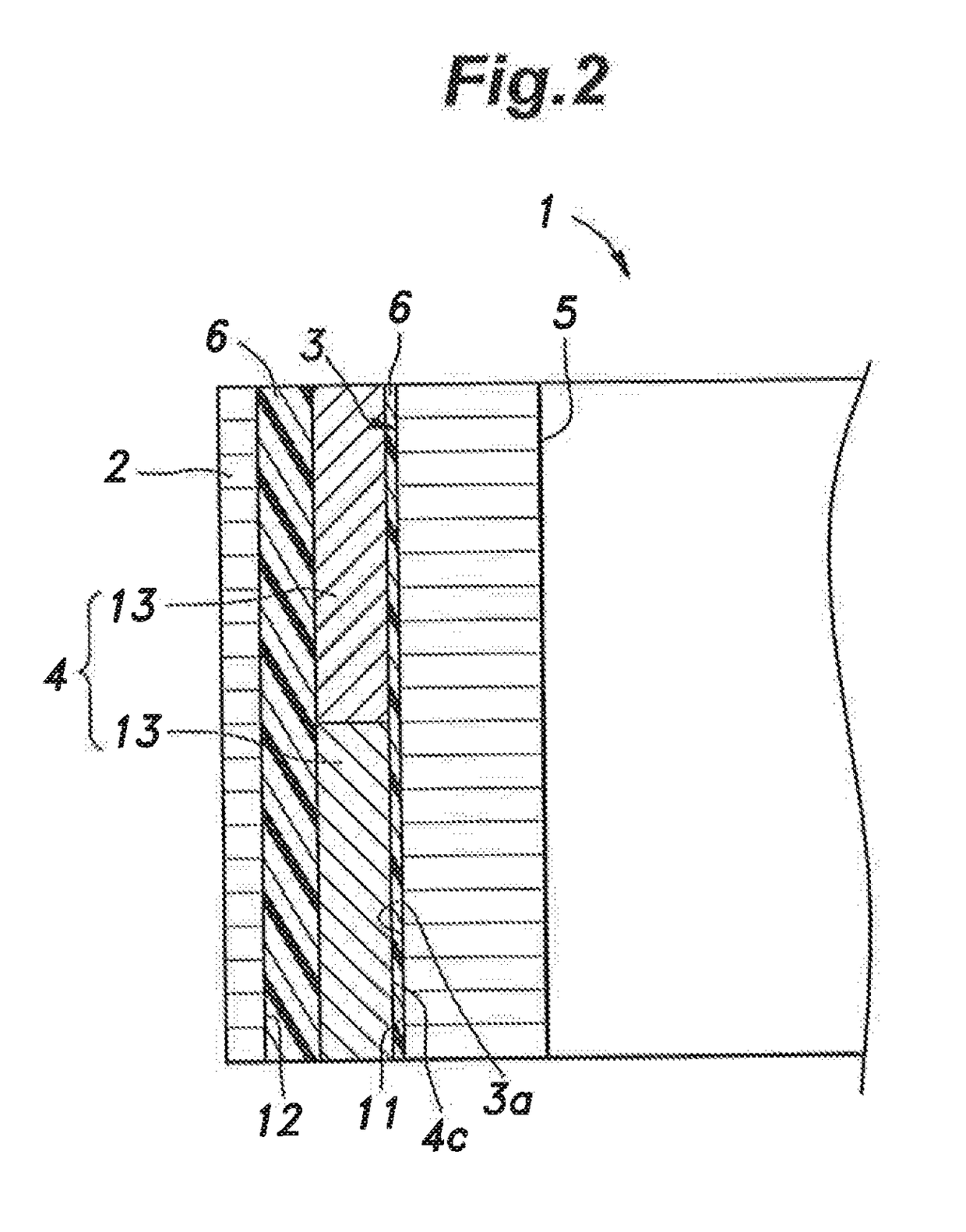
[0029]FIG. 1 is a plan view of a magnet embedded rotor 1 according to an embodiment of the present invention, and FIGS. 2 and 3 are sectional views taken along lines II-II and III-III in FIG. 1, respectively.

[0030]As shown in FIG. 1, a magnet embedded rotor (magnet embedded core) 1 is a constituent part of a motor or the like, and includes a rotor core (motor core) 2 consisting of a laminated iron core, and permanent magnets 4 accommodated respectively in a plurality of magnet insertion holes 3 formed in the rotor core 2. The laminated iron core constituting the rotor core 2 is formed by stacking a plurality of electromagnetic steel plates connected together by a known connecting method (crimping, gluing, laser-welding, etc.). The rotor core 2 is substantially in a shape of an annular ring as seen in plan view, and is provided with an axial hole 5 opened at the center th...


PUM

PropertyMeasurementUnit
Shapeaaaaaaaaaa

Abstract

A resin filling method for a magnet embedded core includes: a fixing step of sandwiching the laminated iron core at axial ends thereof between a first mold and a second mold provided to face each other; and a resin injecting step of injecting a resin into the magnet insertion hole from a resin injecting portion provided in the first mold or the second mold, wherein in the resin injecting step, an end portion of the resin injecting portion is inserted into the magnet insertion hole beyond an axial end surface of the permanent magnet inserted in the magnet insertion hole.

Description

TECHNICAL FIELD[0001]The present invention relates to a resin filling method and a resin filling device for a magnet embedded core in which permanent magnets inserted in magnet insertion holes of a motor core are embedded with a resin.BACKGROUND ART[0002]Conventionally, as a core for motors used in automobiles, electric appliances or the like, a magnet embedded core, in which permanent magnets accommodated in magnet insertion holes formed in a laminated iron core are embedded with a resin, is widely used.[0003]With regard to the magnet embedded core of this kind, it is desired that the permanent magnets can be reliably fixed without deteriorating the properties of the permanent magnets. To meet such demands, as a manufacturing method for a magnet embedded core, for example, a method is known in which after the permanent magnets are inserted into the magnet insertion holes, a mixture of soft magnetic powder and resin is injected and filled into the magnet insertion holes to fix the p...

Claims


Application Information

Patent Timeline
IPC IPC(8): H02K15/03H02K1/27H02K15/12B29C45/14B29C45/00
CPCH02K15/03H02K1/27H02K15/12B29C45/14639B29C45/14065B29C45/0025B29C2045/0027B29L2031/34B29L2031/749B29C45/2708H02K1/276H02K1/2766B29C2045/0036
Inventor OKUDAIRA, HIRONOBUMURAYAMA, TOMOAKIFUKUYAMA, OSAMU
Owner KURODA PRECISION INDS
Why Eureka
Try Eureka