Intraoral Dental Radiological Imaging Sensor

a radiographic imaging and sensor technology, applied in the field of intraoral dental radiographic imaging sensors, can solve the problems of patient discomfort, even greater patient discomfort problem for these sensors, and large space constraints, and achieve the effect of minimizing the dead spa

Active Publication Date: 2018-03-08
MILLER TODD
View PDF2 Cites 2 Cited by
  • Summary
  • Abstract
  • Description
  • Claims
  • Application Information

AI Technical Summary

Benefits of technology

[0039]In an eleventh aspect of the present invention the dental radiological image sensors minimizes the dead space by placing the first and second electrical pads and the wire bonds in the cut corners.

Problems solved by technology

A common complaint and problem during radiographic exams is patient discomfort during the placement of radiographic sensors within the mouth.
This problem is primarily due to the limited space available for proper placement of the sensors within these regions.
This has been a problem since the inception of dental radiography using standard x-ray film technology.
The patient discomfort problem for these sensors is even greater because these devices are rigid by nature and cannot be bent like film to conform to the patient's anatomy.
The space constraints are therefore considerable and it is necessary to try to save as much as possible with regard to the volume of the sensor with a given image surface.
The need for patient comfort entails additional ergonomic constraints.
They are not possible in CMOS technologies, i.e. technologies in which the photosensitive members have active members made from MOS transistors at each pixel in order to convert the photo generated charges into voltage or current and in which the current or voltage signals corresponding to each pixel are transmitted on a column conductor linked with each column of pixels.
This problem is due to the intrinsic design and layout of all digital intraoral sensors with regard to the placement of the dead space that is created as a by-product by parts of the electronic on the sensor.
The reason these radiographs are painful to take is that the imaging plate, whether a film or a sensor (which is stiffer and can cause more pain), must be located such that its mesial end is placed as far forward in the patient's mouth as possible to capture the distal aspect of the canine teeth and the mesial aspect of the premolar teeth in a bitewing or periapical view radiograph.
Once the patient bites down the edges of the film or sensor dig into the tissue on the anterior ascending aspect of the maxillary palate or the lingual aspect of the anterior mandibular region; thus often causing pain when the mesial aspect of the digital sensor is impinging against these very sensitive anatomic regions during a radiographic exam.
The scintillator layer on the electronic interface substrate is very sensitive to shock which can result in irreversible damage and result a concomitant defect in the radiographic image.
However, shock damage to the scintillator layer is usually limited to the four corners of the electronic substrate and specifically to the two corners located at the sensor's distal end.
Existing semiconductor detectors are such designed that all electrical connectivity, except the ground connection, must be implemented at one side of the detector thereby substantially limiting the freedom of designing the device.
One challenge associated with electronic intraoral x-ray sensor is the limited space for obtaining optimized sensor signals.
It is also a further challenge to provide for a high mechanical stability of the sensor under the constraints of limited space for the housing thereof and, more specifically of limited thickness of the sensor as a whole.

Method used


Image

  • Intraoral Dental Radiological Imaging Sensor
  • Intraoral Dental Radiological Imaging Sensor
  • Intraoral Dental Radiological Imaging Sensor

Examples


Embodiment Construction

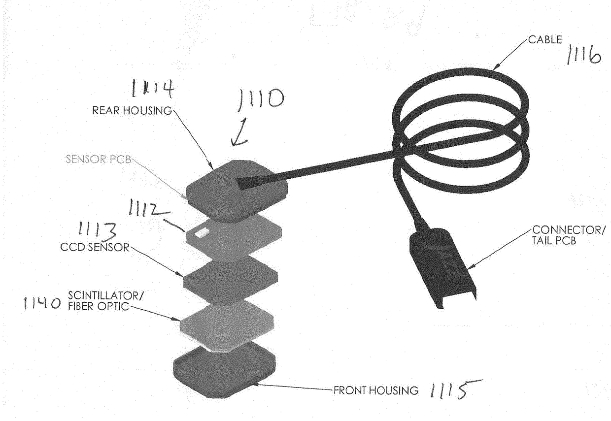
[0072]Referring to FIG. 25 a first intraoral x-ray imaging sensor 1110 includes a housing 1111, an electronic interface substrate 1112 and a semiconductor imager 1113. The housing 1111 has a rear (top) portion 1114 and a front (bottom) portion 1115. The first intraoral x-ray imaging sensor 1110 also includes a data cable 1116 and a cable connecter 1117 which mechanically couples the data cable 1116 to the top portion 1114 of the housing 1111 and electrically couples the data cable 1116 to the electronic interface substrate 1112. The data cable 1116 may be a USB cable with a USB connector 1118. The first intraoral x-ray imaging sensor 1110 may alternatively include a wireless transmitter which is mechanically and electrically coupled to the electronic interface substrate 1112.

[0073]Referring to FIG. 26 in conjunction with FIG. 25 the electronic interface substrate 1112 has a first surface 1119 and second surface 1120 and is substantially rectangular with a mesial end 1121 and a dista...


PUM


Abstract

An intraoral x-ray imaging sensor includes an electronic interface substrate which has a first surface and a second surface and is substantially rectangular with a mesial end and a distal end and a semiconductor imager which is mechanically and electrically coupled to the electronic interface substrate and which has a first surface and a second surface. The semiconductor imager consists of a silicon layer having an array of detector elements formed on its the first surface and is substantially rectangular with a mesial end and a distal end. The electronic interface substrate and the semiconductor imager have a first cut corner and a second cut corner at its the distal end. The second surface of the semiconductor imager is disposed adjacent and contiguous to the first surface of the electronic interface substrate. The intraoral x-ray imaging sensor also includes a plurality of first electrical pads, a plurality of second electrical pads and a plurality of bond wires. The first electrical pads are disposed on the first surface of the electronic interface substrate wherein some of the first electrical pads are disposed adjacent and contiguous to the first cut corner and the remainder of the first electrical pads are disposed adjacent and contiguous to the second cut corner. The second electrical pads are disposed on the first surface of the semiconductor imager wherein some of the of second electrical pads are disposed adjacent and contiguous to the first cut corner and the remainder of the second electrical pads are disposed adjacent and contiguous to the second cut corner. Each bond wire electrically couples one of the first electrical pads to one of the second electrical pads.

Description

BACKGROUND OF THE INVENTION[0001]Field of the Invention[0002]The present invention relates to intraoral radiographic imaging sensors and more particularly to an intraoral radiographic imaging sensor which not only decreases dead space, but also increases a patient's comfort.[0003]Description of the Prior Art[0004]X-rays have been used in dentistry to image teeth and parts of the mouth for many years. In general, the process involves generating x-rays and directing the x-rays at the patient's mouth. The x-rays are attenuated differently by different parts of the mouth (e.g., bone versus tissue) and this difference in attenuation is used to create an image, such as on film or by using electronic image sensor. Radiographs are fundamental to most dental diagnostic procedures. A common complaint and problem during radiographic exams is patient discomfort during the placement of radiographic sensors within the mouth. The majority of these complaints involve the placement of the radiograph...

Claims


Application Information

Patent Timeline
Patent Type & Authority Applications(United States)
IPC IPC(8): A61B6/14H01L27/146H01L23/00H01L27/148
CPCA61B6/145H01L27/14661H01L27/14636H01L24/48H01L27/14663H01L27/14831H01L2224/48227H01L2924/00014H01L2224/73215H01L2224/48091H01L2224/05548H01L24/05H01L24/32H01L24/73H01L2224/4824H01L2224/45099H01L2224/32225H01L2924/00012
Inventor MILLER, TODD
Owner MILLER TODD
Why Eureka
Try Eureka