Valve Manifolds for Simulated Moving Bed Chromatography

a valve manifold and chromatography technology, applied in the field of module chromatography system, can solve the problems of low specific productivity, difficult cleaning of equipment with complex internal geometries, and relatively inefficient mode of operation, and achieve the effect of minimizing dead spa

Active Publication Date: 2021-03-25
CYTIVA SWEDEN AB
View PDF0 Cites 0 Cited by
  • Summary
  • Abstract
  • Description
  • Claims
  • Application Information

AI Technical Summary

Benefits of technology

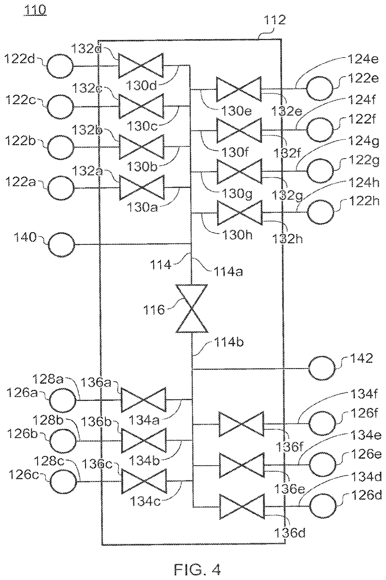
The present invention provides a valve device that allows for flexible connections and minimizes contamination during chromatographic separations. The device includes a manifold body with a central duct and multiple branch ducts arranged in transversely-aligned pairs. Each pair of branch ducts forms a single through-duct that is connected to the central duct by a single branch duct with an access valve. The device also includes a branch valve to control flow between connected through-ducts. This arrangement minimizes dead-space and the device can be used for traditional single-column chromatography processes.

Problems solved by technology

This yields a relatively inefficient mode of operation with a low specific productivity.
Such chromatography processes require large amounts of Adsorbent and large amounts of buffers.
For biotechnology this is undesirable because of the cleaning issues involved.
In this respect, equipment with complex internal geometries is very difficult to clean.
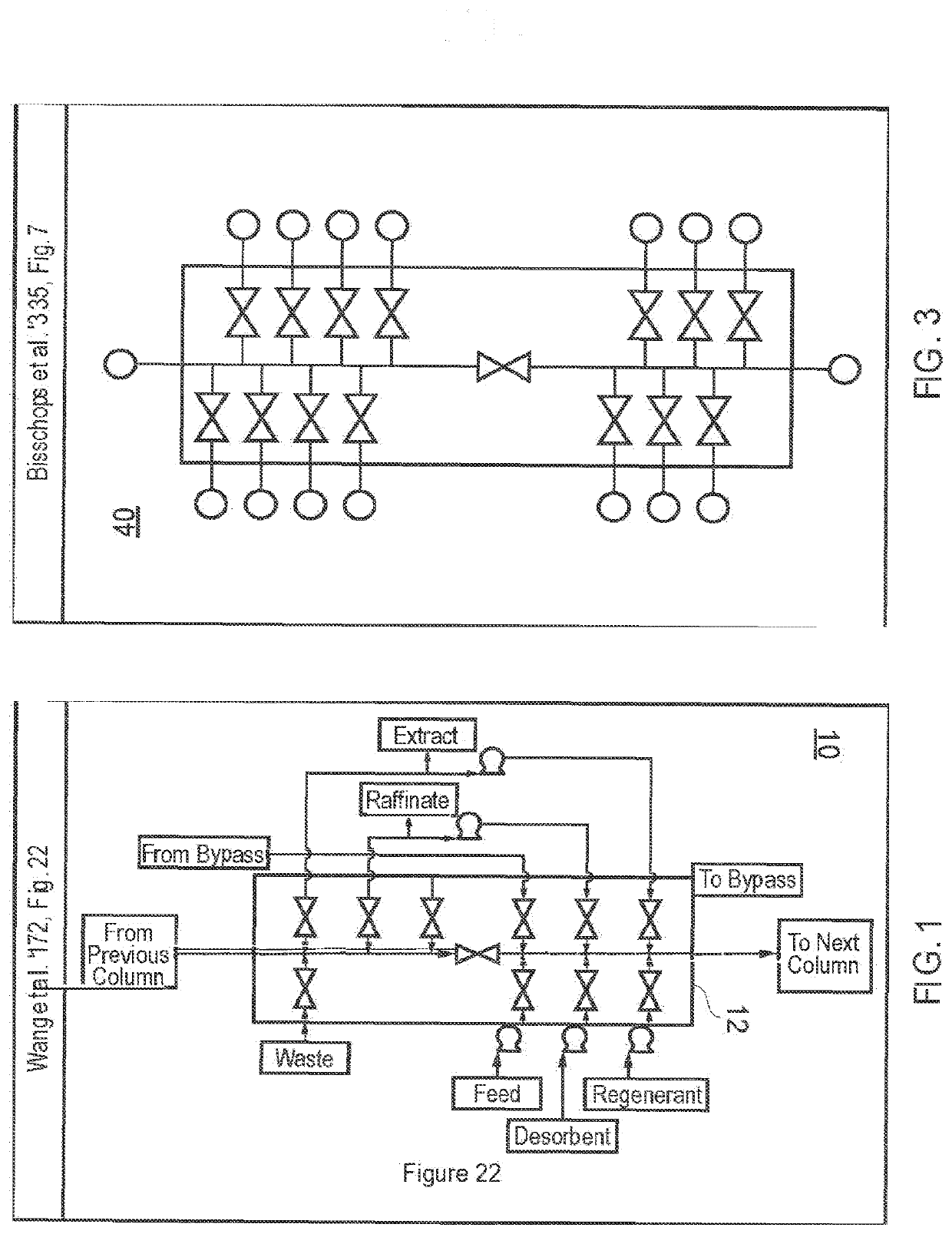
However, the serial connection nature of the Bisschops manifold design necessitates potentially long stretches of conduit for collecting holdup volumes of potentially valuable material fluid.
In SMB, however the columns and bed heights are very short, therefore, the required tubing length gives unfavorable extra holdup volume.
The art therefore lacks a manifold design for SMB applications which reduces potential hold-up volume.

Method used


Image

  • Valve Manifolds for Simulated Moving Bed Chromatography
  • Valve Manifolds for Simulated Moving Bed Chromatography
  • Valve Manifolds for Simulated Moving Bed Chromatography

Examples


Embodiment Construction

Definitions

[0030]In this document, the following terms shall have the following meanings:

[0031]Continuous Multicolumn Chromatography: Continuous Multicolumn Chromatography is a method in which multiple chromatography columns are interconnected to allow continuous operation with respect to the feed solution. This includes among others Simulated Moving Bed chromatography and Merry-Go-Round approaches.

[0032]Adsorbent: The Adsorbent is the stationary phase in the chromatography process. Commonly, this comprises particles, but it may also be a structured packing (e.g. a functionalized membrane or a monolithic structure). The Adsorbent normally comprises a matrix (silica, polymeric, polysaccharides, etc.) and may be functionalized (e.g. in case of ion exchange or affinity chromatography). In the case of a particulate Adsorbent, the Adsorbent may be in a packed bed or may be fluidized during the operation.

[0033]Column: A column is a single module that contains Adsorbent. In the case of a p...


PUM

PropertyMeasurementUnit
chromatographyaaaaaaaaaa
ion exchangeaaaaaaaaaa
affinity chromatographyaaaaaaaaaa

Abstract

Disclosed is a device for chromatographic separations comprising: a manifold comprising a manifold body defining an elongate central duct, the central duct comprising a centrally-located closable duct valve providing selective fluid communication between a first portion of the central duct and an opposed second portion of the central duct, a first plurality of connectors, each connector of the first plurality of connectors for connecting to a distinct chromatographic separation column and / or feed or extraction tubing or to a connector of an adjacent manifold; a second plurality of connectors, each connector of the second plurality of connectors for connecting to a distinct chromatographic separation column and / or feed or extraction tubing or to a connector of an adjacent manifold; wherein said manifold body further defines: a first plurality of branch ducts, each branch duct of which extending from the first portion of the central duct to an individual one of the first plurality of connectors, each of the branch ducts of the first plurality of branch ducts comprising a closable branch valve providing selectable fluid communication between a respective connector and the first portion of the central duct, a second plurality of branch ducts, each branch duct of which extending from the second portion of the central duct to an individual one of the second plurality of connectors, each of the branch ducts of the second plurality of branch ducts comprising a closable branch valve providing selectable fluid communication between a respective connector and the second portion of the central duct; first and second ports in fluid communication with the centrally-located closable duct valve wherein said first port communicates with said first portion of the central duct and said second port communicates with said second portion of said central duct, wherein one of said first and second ports is further positioned to communicate with said central duct at a location between the centrally-located closable duct valve and the first and second plurality of branch ducts, respectively.

Description

CROSS REFERENCE TO RELATED APPLICATIONS[0001]This application is a continuation of U.S. application Ser. No. 15 / 534,540, filed Jun. 9, 2017, allowed, which claims the priority benefit of PCT / EP2015 / 081179 filed on Dec. 23, 2015 which claims priority benefit of U.S. Provisional Patent Application No. 62 / 098,605 filed Dec. 31, 2014. The entire contents of which are hereby incorporated by reference herein.FIELD OF THE INVENTION[0002]The present invention relates to a device for chromatographic separations. In particular, the invention relates to a modular chromatography system for single or multiple columns that is suitable for purification of biopharmaceutical products.BACKGROUND OF THE INVENTION[0003]Chromatography is one of the most important methods for the purification of biotechnological and biopharmaceutical products. This can be based on ion exchange chromatography, affinity chromatography, size exclusion (or gel filtration) chromatography, hydrophobic interaction chromatograph...

Claims


Application Information

Patent Timeline
Patent Type & Authority Applications(United States)
IPC IPC(8): B01D15/18G01N30/20G01N30/88G01N30/46
CPCB01D15/1842G01N30/20G01N30/88G01N30/461G01N30/42G01N30/466G01N2030/205G01N2030/8881G01N30/467G01N30/468
Inventor GEBAUER, KLAUSOLOVSSON, BJORN MARKUS
Owner CYTIVA SWEDEN AB
Why Eureka
Try Eureka