
Racket Grip Reference Point Trainer

a reference point and racket technology, applied in the field of tennis trainers, can solve the problems of cumbersome or unfeasible normal play, cumbersome use, and general usability of hand, wrist and forearm accessories, and achieve the effects of convenient attachment, economic manufacturing, and sufficient durability

Inactive Publication Date: 2018-03-08
KLONTZ DARBY LYNN
View PDF18 Cites 2 Cited by
  • Summary
  • Abstract
  • Description
  • Claims
  • Application Information

AI Technical Summary

Benefits of technology

The invention is a removable training device for tennis players that helps them grip the handle of their racket better. It's like a band with two ridges that act as a stop for the player's fingers when they rotate the racket. The band can be positioned on either side of the racket handle. This training device can be used for any grip and helps improve the player's overall performance.

Problems solved by technology

Unfortunately, many of these devices involving accessories for the hand, wrist and forearm are generally usable for training only and are not feasibly used during normal tennis match play where the player must utilize alternating strokes and rotate the racket to different positions frequently and repeatedly.
Such training devices available today involve bands, straps or other materials that extend from the racket to the player's arm, which are cumbersome or unfeasible for normal play.
Other devices are items that attach directly to the racket grip but protrude significantly and obstructively from the racket grip, inhibiting a player's ability to rotate the racket grip in an unencumbered manner.
Other devices secure the hand in one place firmly against the grip, also making them unfeasible as they inhibit free rotation of the grip.

Method used


Image

  • Racket Grip Reference Point Trainer
  • Racket Grip Reference Point Trainer

Examples


Embodiment Construction

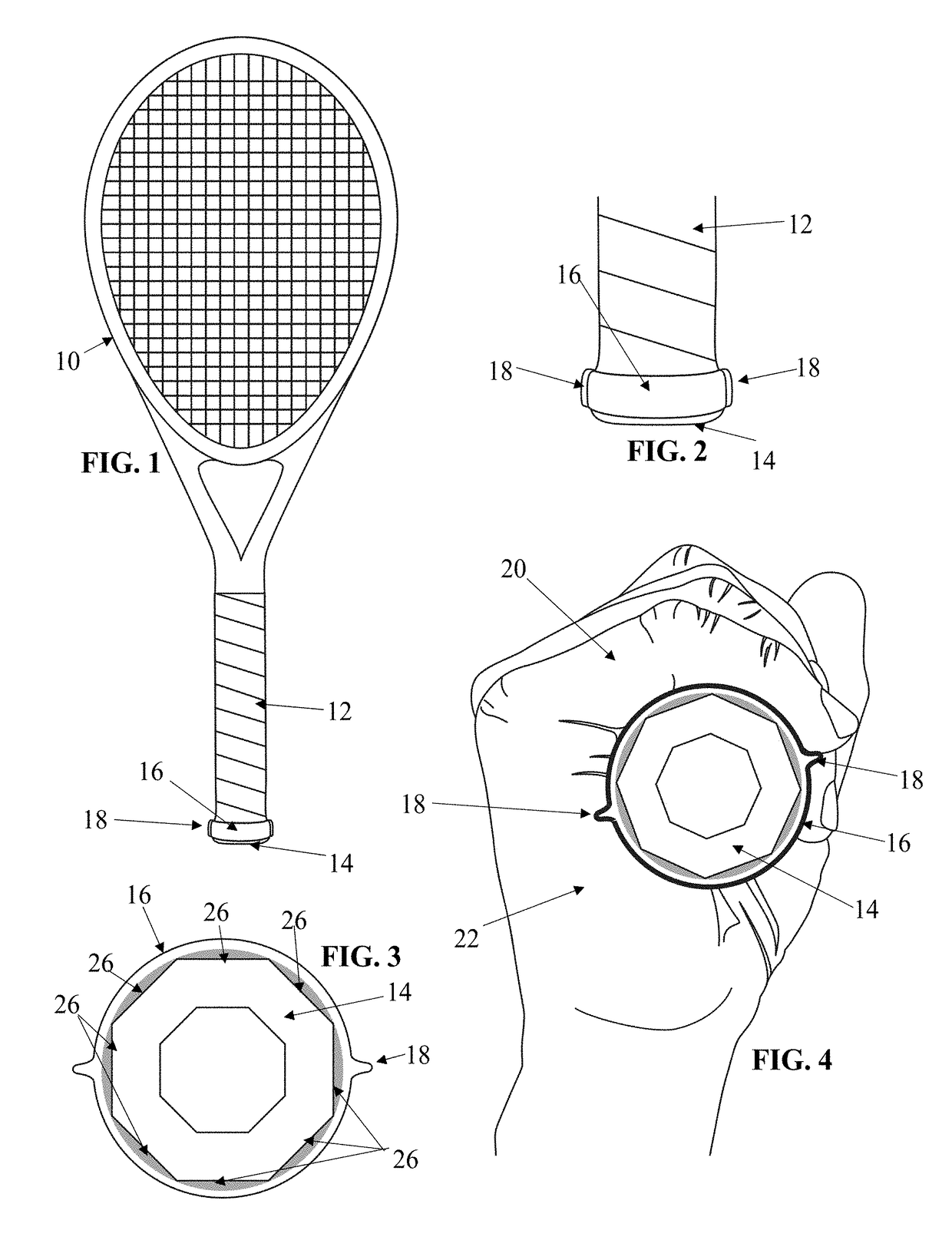
[0036]FIG. 1 is a view of a tennis racket 10 with the invention shown as applied on the racket handle 12 on or near the bottommost end (also called end-cap) 14 of the handle 12. Basically, the invention is composed of a band 16 of varying widths, thicknesses and diameters that is made of elastic material such as rubber, silicone or similar materials and can be easily applied and removed from the racket by stretching and applying over the end-cap 14 of the racket handle 12.

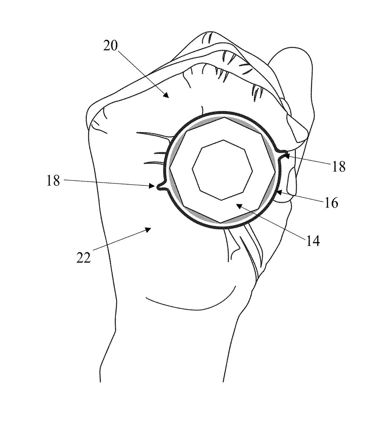
[0037]As shown more clearly in FIGS. 3 and 4, included on the band 16 at two points equidistant from each other on the circular band are “ridges”18 that protrude from the exterior surface of the band and act as a tactile physical stop for a player's pinky finger 20 as the racket is rotated among various types of grips during play. When the invention is applied and the hand grips the racket handle, the pinky finger 20 and the outer edge of the hand 22 (specifically, the region including the Musculus abductor digiti ...


PUM


Abstract

An attachment to the handle of a racket that tactically indicates to a player whether his / her hand has properly gripped the handle of a racket for a desired tennis stroke (e.g., forehand, backhand, etc.). The attachment is a band composed of rubber or a similar elastic material positioned around of the racket handle positioned such that the outer edge of the player's hand and smallest finger of the hand (also known as the “pinky” finger) rest on top of the band. The band further includes two “ridges” circumferentially equidistant from each other on the circular wrap, each protruding from the exterior the band to provide a surface against which the end of the player's finger will abut to provide a tactile stopping point for the player's hand when rotating the racket handle so as to achieve consistent hand placement for a designated grip as the player transitions from one grip to another during play.

Description

CROSS-REFERENCE TO RELATED APPLICATIONS[0001]This application claims the benefit of U.S. Provisional Application No. 62 / 384,910, filed 8 Sep. 2016.STATEMENT REGARDING FEDERALLY SPONSORED RESEARCH OR DEVELOPMENT[0002]Not applicable.THE NAMES OF THE PARTIES TO A JOINT RESEARCH AGREEMENT[0003]Not applicable.INCORPORATION-BY-REFERENCE OF MATERIAL SUBMITTED ON A COMPACT DISC OR AS A TEXT FILE VIA THE OFFICE ELECTRONIC FILING SYSTEM (EFS-WEB)[0004]Not applicable.STATEMENT REGARDING PRIOR DISCLOSURES BY THE INVENTOR OR A JOINT INVENTOR[0005]Not applicable.BACKGROUND OF THE INVENTION[0006]Tennis is a very popular sport played around the world by people of all ages. In order to become a skilled tennis player, it is necessary to learn a variety of tennis racket grip types. Different grips are typically used for various types of tennis strokes, such as forehands, backhands, volleys, serves, etc. The type of tennis racket grip used directly affects and controls the angle of the racket during th...

Claims


Application Information

Patent Timeline
IPC IPC(8): A63B60/10A63B69/38A63B60/14A63B71/06
CPCA63B60/10A63B69/38A63B60/14A63B71/0619A63B2209/00A63B2102/02A63B2071/0655A63B49/035A63B49/08A63B60/16A63B60/08
Inventor KLONTZ, DARBY LYNN
Owner KLONTZ DARBY LYNN
Learn More