Method, system and apparatus for activating a lighting module using a buffer load module

a technology of buffer load and lighting module, which is applied in the field of lighting control, can solve the problems of led module forward voltage fluctuations, complex design of led modules, and inability to be simpl

Active Publication Date: 2018-03-08
ARKALUMEN
View PDF4 Cites 17 Cited by
  • Summary
  • Abstract
  • Description
  • Claims
  • Application Information

AI Technical Summary

Benefits of technology

[0010]According to a first broad aspect, the present invention is a control apparatus adapted to be coupled between a power source and a lighting module. The power source is operable to generate an output voltage at a power source output. If the lighting module is coupled to the power source output, the power source is operable to generate a first output voltage to maintain a constant current level flowing through the lighting module and, if the lighting module is not coupled to the power source output, the power source is operable to generate a second output voltage at a maximum voltage limit for the power source. The control apparatus comprises a voltage control module and a controller. The voltage control module is adapted to be coupled to the power source output and is operable to convert the output voltage generated by the power source to a controlled voltage independent of whether the output voltage generated by the power source is the first output voltage or the second output voltage. The voltage control module has a maximum input voltage equal to or greater than the maximum voltage limit of the power source. The controller is powered by the controlled voltage and operable to selectively couple the lighting module to the power source output.

Problems solved by technology

Perfectly matching the DC voltage output of a constant voltage driver with a particular forward voltage for a series of LEDs is not simple and could add complexity to the design of the LED modules.
Further, fluctuations in the forward voltage of LEDs will occur if thermal temperature changes occur and long wires used to connect the LED modules may increase voltage drops.
These fluctuations will result in load requirements changing while the constant voltage driver maintains the same voltage output, thus causing fluctuations in the current flowing through the LEDs.
The result of this situation is an inconsistent light output intensity which is not desired.
A problem with the commoditization of the constant current drivers is that there is little development on how to implement advanced control features using these simple AC to DC converters.
None of these features can easily be implemented using the simple constant current drivers that are becoming the standard components in LED light fixtures.

Method used


Image

  • Method, system and apparatus for activating a lighting module using a buffer load module
  • Method, system and apparatus for activating a lighting module using a buffer load module
  • Method, system and apparatus for activating a lighting module using a buffer load module

Examples


Embodiment Construction

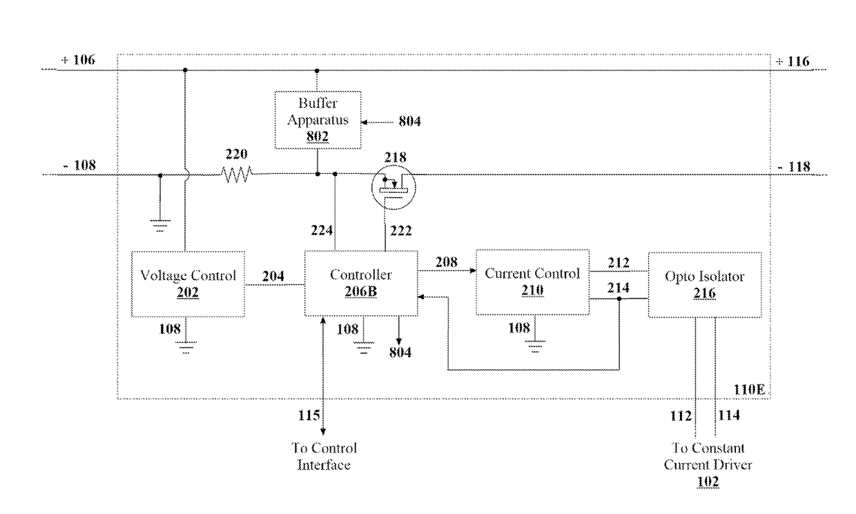
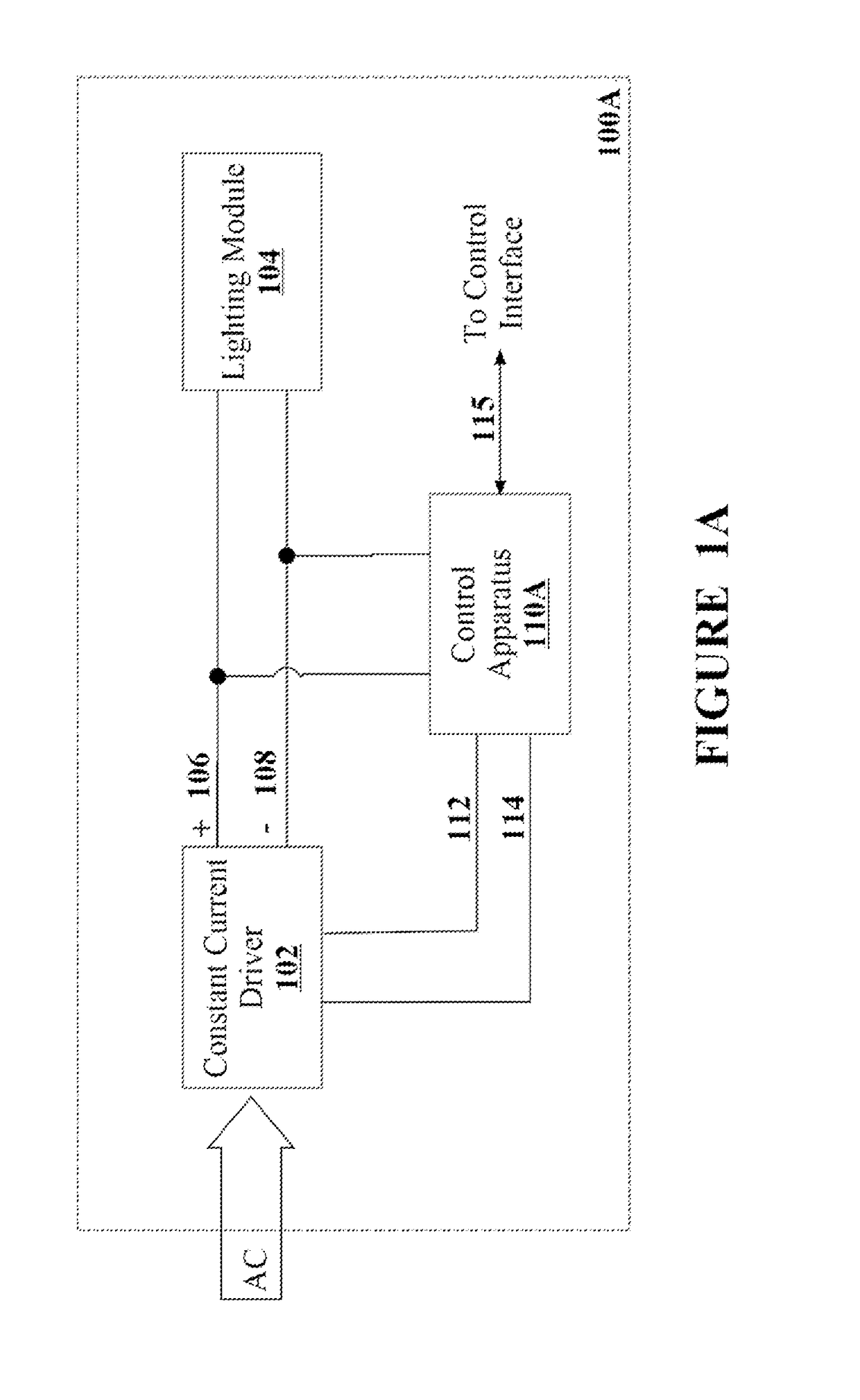
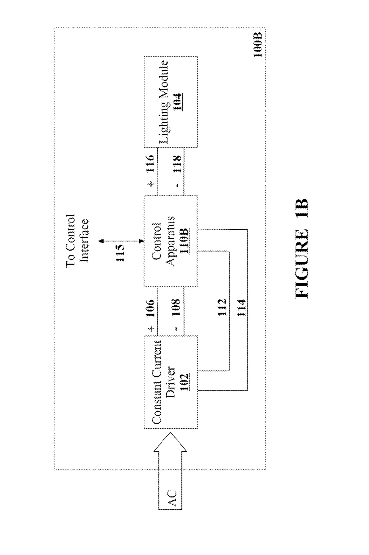
[0065]The present invention is directed to circuit and apparatus for controlling an output of a constant current driver. A control apparatus is coupled between a constant current driver and a load, such as a lighting module, in order to add functionality to the overall system. The control apparatus is powered by the constant current driver and may control the dimming of the constant current driver by controlling the 0-10V dim input into the driver. The control apparatus may comprise one or more switching elements between the constant current driver and the load. The control apparatus may interface with external devices or communication networks in order to receive control commands or information that may be used for control purposes. Overall, the control apparatus is implemented into the system to enable added-value features that the constant current driver would otherwise not be able to implement.

[0066]The embodiments described are directed to implementations of constant current dr...


PUM


Abstract

Control apparatus and system for controlling an output of a constant current driver are disclosed. A control apparatus is coupled between a constant current driver and a load, such as a lighting module, in order to add functionality to the overall system. The control apparatus is powered by the constant current driver and may control the dimming of the constant current driver by controlling the 0-10V dim input into the driver. The control apparatus may comprise one or more switching elements between the constant current driver and the load to allow for mixing of groups of LEDs of various colors or color temperatures. The control apparatus may include a buffer load to mitigate negative impacts of turning on the lighting module after a period of deactivation. The control apparatus can also be adapted to operate as a dim-to-warm module within a lighting apparatus.

Description

CROSS-REFERENCE TO RELATED APPLICATION[0001]The present application is a continuation-in-part of and claims the benefit under 35 USC 120 of U.S. patent application Ser. No. 15 / 052,873 entitled “CIRCUIT AND APPARATUS FOR CONTROLLING A CONSTANT CURRENT DC DRIVER OUTPUT” by Briggs filed on Feb. 24, 2016 which claims the benefit under 35 USC 119(e) of U.S. Provisional Patent Application 62 / 157,460 filed on May 5, 2015. The present application hereby incorporated both patent applications by reference herein.FIELD OF THE INVENTION[0002]The invention relates generally to lighting controls and, more particularly, to method, system and apparatus for activating a lighting module using a buffer load module.BACKGROUND[0003]Light Emitting Diodes (LEDs) are increasingly being adopted as general illumination lighting sources due to their high energy efficiency and long service life relative to traditional sources of light such as incandescent, fluorescent and halogen. Each generation of LEDs are p...

Claims


Application Information

Patent Timeline
Patent Type & Authority Applications(United States)
IPC IPC(8): H05B33/08H05B37/02H05B44/00
CPCH05B33/0845H05B37/02H05B33/0857H05B45/10H05B45/20H05B47/10H05B45/382H05B47/17H05B45/375H05B47/195
Inventor GIRARD, JULIENVERMETTE, YANMURRAY, SEAN MACLEANBRIGGS, GERALD EDWARD
Owner ARKALUMEN
Why Eureka
Try Eureka