Cartridge for use with a vaporizer device

a vaporizer device and cartridge technology, applied in the field of cartridges for use with vaporizer devices, can solve the problems of unstable electrical contacts, difficult to determine, and the cylindrical shape may not be optimal, and achieve the effect of preventing rolling and ensuring mechanical and electrical connection

Active Publication Date: 2018-03-15
JUUL LABS INC
View PDF0 Cites 19 Cited by
  • Summary
  • Abstract
  • Description
  • Claims
  • Application Information

AI Technical Summary

Benefits of technology

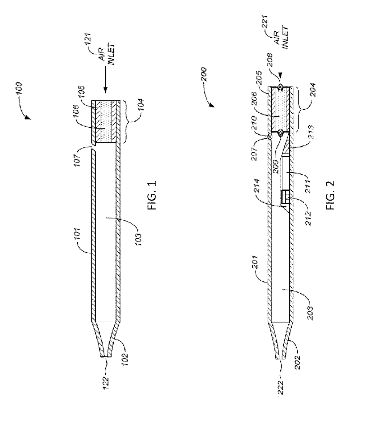
[0010]As will be illustrated and described below, the cannula forms a passage for the vapor from the heater to the mouthpiece, and typically passes through the tank so that it is surrounded by vaporizable fluid in the tank; this may help to regulate the temperature of the vapor within the cannula, providing a substantially improved vaping experience. The cannula may be visible through the window / notch. Although having the cannula visible in the window may obscure the view into the tank, it also helps provide a visual reference for the liquid level that makes it much easier for a user to get a quick and accurate understanding of the actual level of vaporizable material within the tank.
[0011]In general, the mouthpiece may be opaque and may fit over the top / end of the transparent tank (storage compartment) and may be secured over the end of the storage compartment. This may allow the mouthpiece to form a lip or rim formed by the distal edge of the mouthpiece over the storage compartment that helps guide and helps secure the cartridge in the cartridge receptacle of the vaporizer.
[0013]Any of these cartridges may also include a gap on the side of the cartridge to mate with a detent on the vaporizer. The gap (also referred to herein as a locking gap) may be a channel, pit, hole, divot, etc. in the sides of the elongate and flattened storage compartment. These gaps may act as a mechanical lock to secure the cartridge in the vaporizer, and may also provide tactile and / or audible\feedback (producing a click or snap) when the cartridge is properly seated in the cartridge receptacle so that there is a robust mechanical and electrical connection between the cartridge and the vaporizer.
[0014]In general, the apparatuses described herein also include vaporizers and cartridges in which the cartridge is inserted into a cartridge receptacle at the proximal end of the vaporizer so that the mouthpiece projects out of the proximal end. Overall, the combined cartridge and vaporizer may have an elongate, flattened shape that prevents rolling when the apparatus is placed on a table or other flat surface so that is is lying flat on the surface. As mentioned, the body of the vaporizer, and particularly the proximal edge of the cartridge receptacle, may include a notch or cut-out portion that forms a window into the (transparent) cartridge when the cartridge is held within the cartridge receptacle. Similarly, the cartridge receptacle portion of the vaporizer may include a coupling to secure the cartridge within the cartridge receptacle even when it projects out of the end of the vaporizer, and even when the entire apparatus is held within a user's mouth only at the mouthpiece of the cartridge. Although the majority of the weight of the apparatus is in the vaporizers (near the distal end of the apparatus), the coupling, which may be two or more detents on the side of the cartridge receptacle and / or a magnetic coupling, may hold the cartridge secured in position even where the electrical coupling is a biased connection (such as a pogo pin) that would tend to push the cartridge out of the cartridge receptacle.
[0073]The first pair of heater contacts may further comprise: a formed shape that comprises a tab having a flexible spring value that extends out of the heater to complete a circuit with the device body. The heater contacts may be configured to mate with a second pair of heater contacts in a cartridge receptacle of the device body to complete a circuit. The first pair of heater contacts may also be a heat sink that absorbs and dissipates excessive heat produced by the resistive heating element. The first pair of heater contacts may be a heat shield that protect the heater chamber from excessive heat produced by the resistive heating element.

Problems solved by technology

Although mimicking the cylindrical look of traditional cigarettes may have marketing advantages because of a preexisting familiarity with this shape and potentially feel of the product, the cylindrical shape may not be optimal.
However, a number of surprising disadvantages may result in this configuration.
For example the use of a cartridge at the proximal end of the device, which is also held by the users mouth, has been found to cause instability in the electrical contacts, particularly with cartridges of greater than 1 cm length.
Further, there may be difficulties in determining the amount of vaporizable material within the cartridge, sufficiently cooling or otherwise processing the vapor generated by a heater located in the cartridge, and easily and quickly securing the cartridge into the vaporizer when force may be applied by a user's mouth at the proximal mouthpiece when a user holds the device either just by the mouth or using the mouth at the proximal end and a hand on the more distal body of the vaporizer.

Method used


Image

  • Cartridge for use with a vaporizer device
  • Cartridge for use with a vaporizer device
  • Cartridge for use with a vaporizer device

Examples


examples

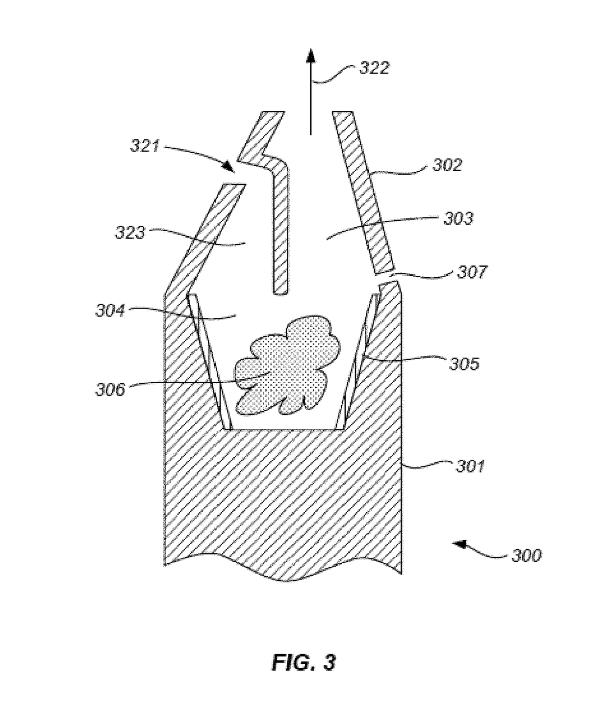
[0348]Any of the cartridges described in the figures and description above may include an elongate and flattened storage compartment for holding a vaporizable material and a mouthpiece at the proximal end of cartridge. In particular, FIGS. 5-7B, 8B, 9, 11-15, and 16C show examples of a cartridge for use with a vaporizer device that includes an elongate and flattened storage compartment (see, element 32 in FIG. 7B and element 32a in FIG. 9) configured to hold a liquid vaporizable material, wherein the liquid vaporizable material is visible through the storage compartment, further wherein the storage compartment comprises a distal end and a proximal end, and a first side extending between the distal end and the proximal end. In each of these examples the cartridge also includes an opaque mouthpiece (e.g., 31 in FIGS. 7B and 8B) that is secured over the proximal end of the storage compartment, the opaque mouthpiece having a front side adjacent to the first side of the storage compartme...


PUM


Abstract

Cartomizers (cartridges) that have a mouthpiece, a heater / vaporizer (e.g., heating element, wick), and a transparent / translucent tank (fluid reservoir) to hold the vaporizable material (typically a nicotine solution), in which the cartridge is flattened and has a window into the tank through the mouthpiece so that the liquid level is visible; the window can be an opening through the mouthpiece or it can be a notch up into the mouthpiece. A cannula (e.g., tube) runs through the tank, and connects the heater / vaporizer to an opening in the mouthpiece.

Description

CROSS REFERENCE TO RELATED APPLICATIONS[0001]This patent application is a continuation of U.S. patent application Ser. No. 15 / 257,748, filed Sep. 6, 2016 and entitled “CARTRIDGE FOR USE WITH A VAPORIZER DEVICE”, which is a continuation-in-part of U.S. patent application Ser. No. 14 / 581,666, filed on Dec. 23, 2014, and entitled “VAPORIZATION DEVICE SYSTEMS AND METHODS”, which claims priority to U.S. Provisional Patent Application No. 61 / 920,225, filed Dec. 23, 2013, U.S. Provisional Patent Application No. 61 / 936,593, filed Feb. 6, 2014, and U.S. Provisional Patent Application Ser. No. 61 / 937,755 filed Feb. 10, 2014. U.S. patent application Ser. No. 15 / 257,748 also claims priority to U.S. provisional patent application 62 / 294,285, filed on Feb. 11, 2016 and entitled “FILLABLE ELECTRONIC CIGARETTE CARTRIDGE AND METHOD OF FILLING”, U.S. provisional patent application 62 / 294,281, filed on Feb. 11, 2016 and entitled “SECURELY ATTACHING CARTRIDGES FOR VAPORIZER DEVICES”, International Desi...

Claims


Application Information

Patent Timeline
Patent Type & Authority Applications(United States)
IPC IPC(8): A24F47/00H05B3/44A24F7/00F22B1/28A24B15/16H05B1/02A24F40/10A24F40/20A24F40/42A24F40/46A24F40/70
CPCH05B2203/021H05B3/44H05B2203/022A24F7/00F22B1/284A24B15/167A24F47/008H05B1/0244A61M15/06A61M2205/3653A61M2205/8206A61M11/042A24F40/46A24F40/10A24F40/70A24F40/42A24F40/20A61M15/0015A61M15/0016
Inventor MONSEES, JAMESBOWEN, ADAMHATTON, NICHOLAS JAYCHRISTENSEN, STEVENLOMELI, KEVINATKINS, ARIELKELLER, AARON
Owner JUUL LABS INC
Why Eureka
Try Eureka