Vehicle automatic emergency braking system

a technology of automatic emergency braking and vehicle, which is applied in the direction of braking system, braking components, transportation and packaging, etc., can solve the problems of rubber flexible lines failing, metal parts rusting, and hydraulic braking systems not being very well maintained

Inactive Publication Date: 2018-03-15
MAGNA ELECTRONICS
View PDF5 Cites 12 Cited by
  • Summary
  • Abstract
  • Description
  • Claims
  • Application Information

AI Technical Summary

Problems solved by technology

Over years of use, the hydraulic braking systems may not be very well maintained and the metal parts may rust and the rubber flexible lines may fail.
If pressure is lost in the system, the brakes will not work and the driver may be faced with a situation where the driver has to manually downshift the vehicle transmission and / or manually apply the parking brake of the vehicle (typically only at the rear wheels) in order to slow down and stop the vehicle.

Method used


Image

  • Vehicle automatic emergency braking system
  • Vehicle automatic emergency braking system
  • Vehicle automatic emergency braking system

Examples


Embodiment Construction

[0009]The vehicle driver assist system and / or emergency braking system operates to control braking or slowing of a vehicle when the system determines that there is a failure or partial failure of the primary or hydraulic braking system of the vehicle. The braking system involves the use of an electric parking brake and / or emergency brake of the vehicle in a new way and a software strategy for using the transmission to decelerate the vehicle when an emergency failure of the hydraulic braking system occurs.

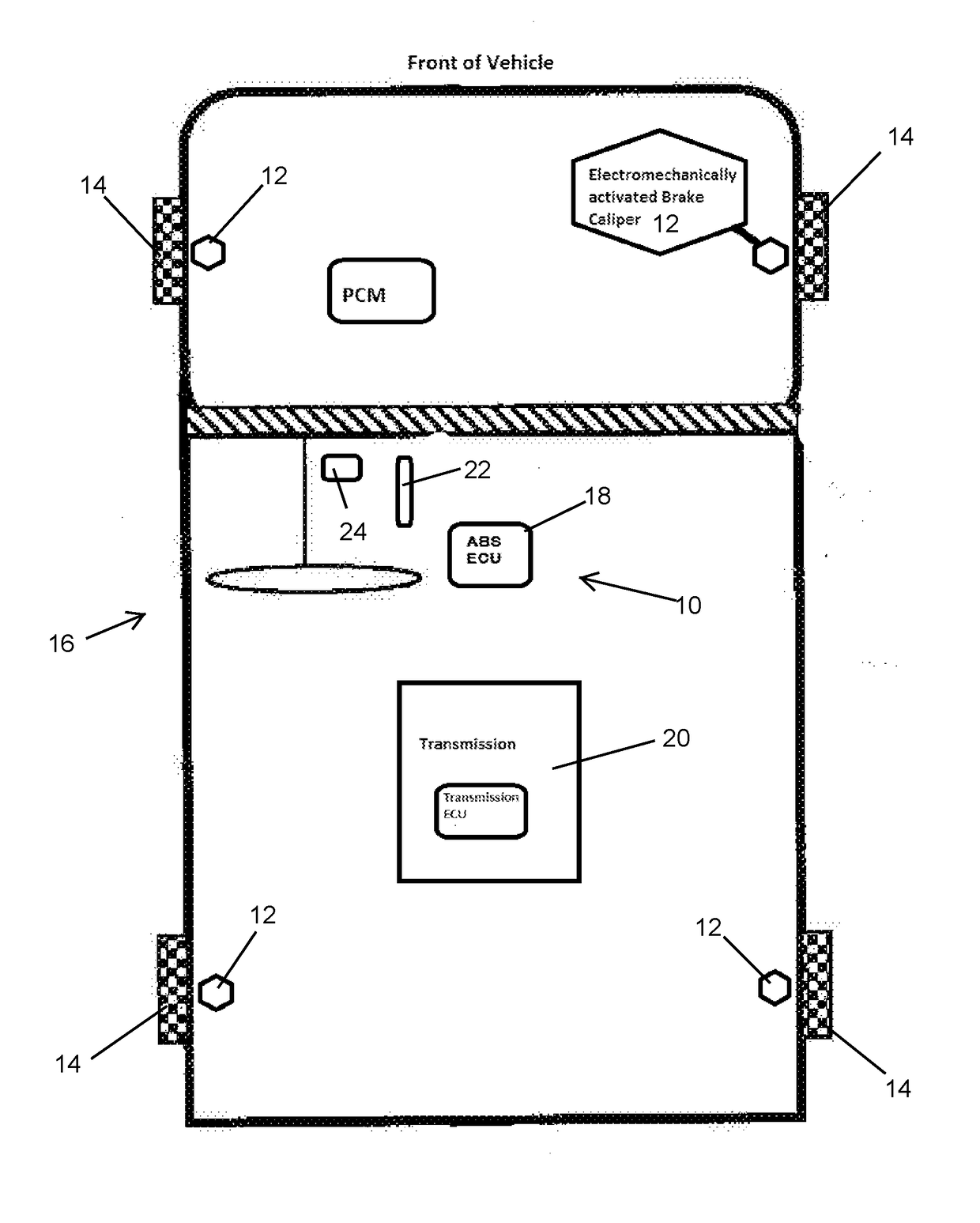
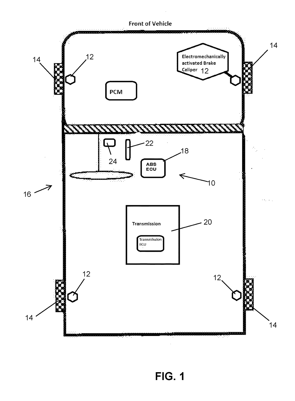
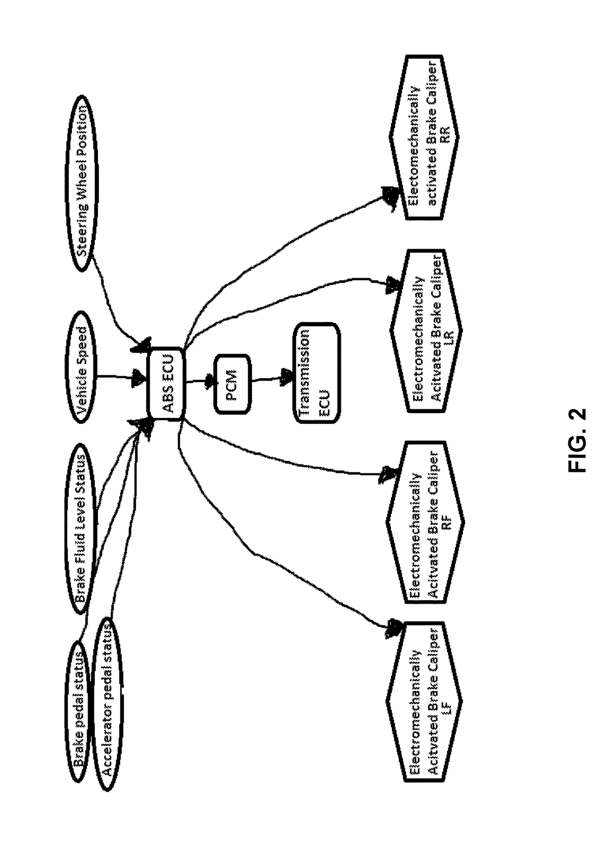
[0010]Referring now to the drawings and the illustrative embodiments depicted therein, the braking system 10 comprises an electromechanical brake device or caliper 12 disposed at each wheel 14 of the vehicle 16 (and operable to brake or slow rotation of the respective wheel) and a controller 18. The controller 18 is operable to actuate or control the electromechanical brake devices 12 responsive to a determination that the primary or hydraulic brake system of the vehicle has a failu...


PUM


Abstract

An automatic braking system of a vehicle includes an auxiliary braking device at at least two wheels of the vehicle. A controller is operable to control the auxiliary braking devices responsive to an input from a brake fluid pressure sensor and an input from a brake pedal position sensor. Responsive to the inputs being indicative of a brake pedal of the vehicle being applied and a brake fluid pressure of brake fluid of a hydraulic brake system of the vehicle being below a threshold level for the degree of application of the brake pedal, the controller determines that there is at least a partial failure of the hydraulic brake system of the vehicle and controls the auxiliary braking devices to slow down the vehicle.

Description

CROSS REFERENCE TO RELATED APPLICATION[0001]The present application claims the filing benefits of U.S. provisional application Ser. No. 62 / 385,407, filed Sep. 9, 2016, which is hereby incorporated herein by reference in its entirety.FIELD OF THE INVENTION[0002]The present invention relates generally to a vehicle braking system for a vehicle and, more particularly, to a vehicle emergency braking system.BACKGROUND OF THE INVENTION[0003]Brake systems for vehicles are typically hydraulic brake systems. Over years of use, the hydraulic braking systems may not be very well maintained and the metal parts may rust and the rubber flexible lines may fail. If pressure is lost in the system, the brakes will not work and the driver may be faced with a situation where the driver has to manually downshift the vehicle transmission and / or manually apply the parking brake of the vehicle (typically only at the rear wheels) in order to slow down and stop the vehicle. All this may have to be done while ...

Claims


Application Information

Patent Timeline
Patent Type & Authority Applications(United States)
IPC IPC(8): B60T8/92
CPCB60T8/92B60T7/12B60T8/885B60T2270/82B60T17/226B60T2270/404B60T13/746B60T7/042B60T7/22B60T8/3255B60T13/662B60T13/686B60T13/741B60T2201/022B60T2260/04B60T2270/402
Inventor RENAUD, RONALD R.
Owner MAGNA ELECTRONICS
Why Eureka
Try Eureka