
System and method for condition-based monitoring of turbine filters

a technology of condition-based monitoring and filter filter, which is applied in the field of system and method for condition-based monitoring of filter filter, can solve the problems of affecting the output of the turbine system, affecting the use of components and subsystems, and accumulation of substances,

Inactive Publication Date: 2018-03-15
GENERAL ELECTRIC CO
View PDF0 Cites 20 Cited by
  • Summary
  • Abstract
  • Description
  • Claims
  • Application Information

AI Technical Summary

Benefits of technology

The patent text describes a filter degradation prediction model that can estimate the rate at which filters in a turbine system will degrade. By monitoring the performance of the filters and taking preventive action, the model can help to maintain the efficiency of the filter system, reduce downtime for the turbine system, and improve performance by reducing pressure drops.

Problems solved by technology

Over time, the components and subsystems may degrade from use, accumulation of substances, or the like.
For example, filters in a filter house of a turbine system may degrade by accumulating dust, thereby causing a pressure drop in an inlet duct structure that is undesirable.
In another example, the compressor of a turbine system may also degrade by accumulating dust, thereby affecting the output of the turbine system.
However, following a static schedule may lead to inefficient resource usage by replacing a component before it has actually reached a degraded state that affects the performance of the turbine system.
Likewise, following the static schedule to replace a component after it has already reached a degraded state may result in operating inefficiencies and other compressor operation issues, such as vibration and reduction in surge margin, in the turbine system.

Method used


Image

  • System and method for condition-based monitoring of turbine filters
  • System and method for condition-based monitoring of turbine filters
  • System and method for condition-based monitoring of turbine filters

Examples


Embodiment Construction

[0013]One or more specific embodiments of the present subject matter will be described below. In an effort to provide a concise description of these embodiments, all features of an actual implementation may not be described in the specification. It should be appreciated that in the development of any such actual implementation, as in any engineering or design project, numerous implementation-specific decisions must be made to achieve the developers' specific goals, such as compliance with system-related and business-related constraints, which may vary from one implementation to another. Moreover, it should be appreciated that such a development effort might be complex and time consuming, but would nevertheless be a routine undertaking of design, fabrication, and manufacture for those of ordinary skill having the benefit of this disclosure.

[0014]When introducing elements of various embodiments of the present subject matter, the articles “a,”“an,”“the,” and “said” are intended to mean...


PUM

PropertyMeasurementUnit
Temperatureaaaaaaaaaa
Pressureaaaaaaaaaa
Sizeaaaaaaaaaa

Abstract

In one embodiment, a turbine system includes an intake section including a filter house, the filter house including at least one filtration stage, each of the at least one filtration stage, including a filter. The turbine system also includes one or more sensors disposed in the intake section, and a processor configured to receive performance data related to testing conditions of the intake section, sensor data from the one or more sensors, local conditions data, or some combination thereof, predict a filter degradation rate for the filter using a filter degradation prediction model that provides a function of performance of the filter based on the performance data, the sensor data, the local conditions data, or some combination thereof, and perform one or more preventative actions based on the filter degradation rate prediction.

Description

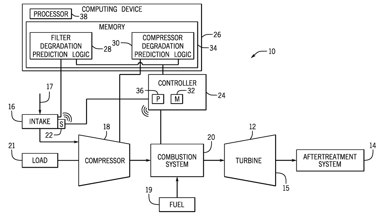
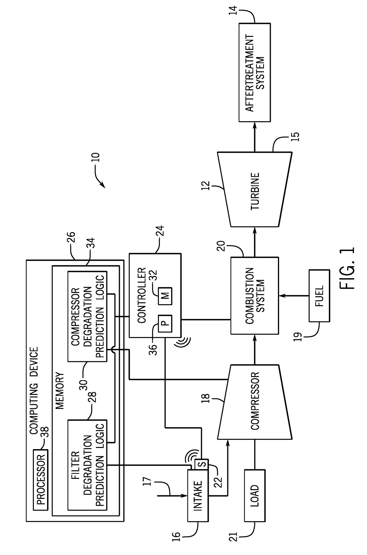
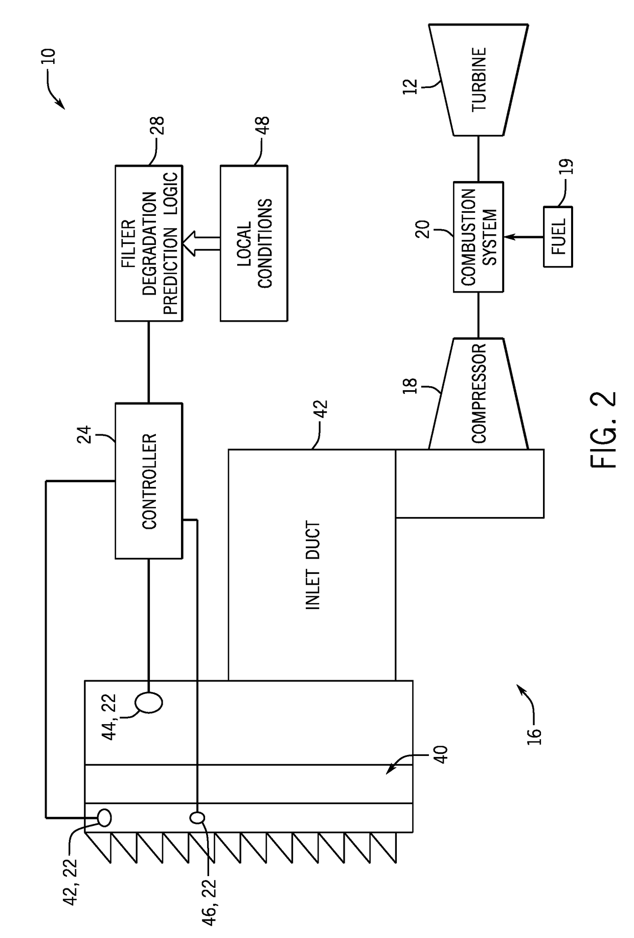
BACKGROUND OF THE INVENTION[0001]The subject matter disclosed herein relates to turbomachinery, and more particularly, to predicting degradation rates of components of turbomachinery using condition-based monitoring.[0002]Turbomachine systems (e.g., turbine systems) may include a variety of components and subsystems participating in a process. For example, a turbomachine may include a load, a shaft, a filter house, fuel lines, combustors, turbine, exhaust systems, and so forth. The components and subsystems may operate in conjunction to produce work output by spinning the shaft that drives the load (e.g., electric generator). Over time, the components and subsystems may degrade from use, accumulation of substances, or the like. For example, filters in a filter house of a turbine system may degrade by accumulating dust, thereby causing a pressure drop in an inlet duct structure that is undesirable. In another example, the compressor of a turbine system may also degrade by accumulatin...

Claims


Application Information

Patent Timeline
IPC IPC(8): F01D21/00G01M15/14B01D46/00B01D46/44
CPCF01D21/003G01M15/14B01D46/0068B01D46/008F05D2260/607B01D46/442B01D46/446B01D46/448B01D46/0086F02C7/05F02C7/057F05D2270/44F05D2260/81F05D2260/82F01D25/002F02C7/055G05B23/0283F05D2230/72F05D2260/80G05B23/0254B01D46/71B01D46/88
Inventor ZHANG, HUAKIPPEL, BRADLYTRAYHAN, DAVIDHU, IRIS
Owner GENERAL ELECTRIC CO
Learn More