Methods And System For Demand-Based Control Of A Combination Boiler

a technology of demand-based control and combination boiler, which is applied in the direction of fluid heaters, heating types, lighting and heating apparatus, etc., can solve the problems of increasing the cost and complexity of providing a dhw flow sensor to a combination boiler, affecting the heating of dhw output, and affecting the operation of current combination boiler implementation

Active Publication Date: 2018-03-15
LOCHINVAR
View PDF3 Cites 12 Cited by
  • Summary
  • Abstract
  • Description
  • Claims
  • Application Information

AI Technical Summary

Benefits of technology

The invention described in this patent may help solve the problems of excessive noise and limited frequency range in conventional wireless devices. It achieves this by introducing a new technique that reduces the impact of interference between signals. This technique can improve the performance of wireless devices and make them more reliable and efficient.

Problems solved by technology

Current combination boiler implementations suffer drawbacks associated with initially and continuously undershooting and overshooting heated water temperatures when attempting to provide DHW at a desired set point temperature.
However, providing a DHW flow sensor adds both cost and complexity to a combination boiler.
Furthermore, flow sensors typically have a minimum flow rate detection threshold, below which the flow sensor does not detect a current flow rate.
Thus, low DHW output flow rates are not detected and heated DHW output may be significantly delayed or DHW output may be concluded before heated water is provided.
Problems also arise with combination boilers that initialize a burner input rate (e.g., fan speed) only on a proportional term.
For example, if a DHW output temperature is close to a set point temperature when the burner fires, an input fan of the burner may initialize at a low input rate, causing a significant DHW output temperature undershoot.

Method used


Image

  • Methods And System For Demand-Based Control Of A Combination Boiler
  • Methods And System For Demand-Based Control Of A Combination Boiler
  • Methods And System For Demand-Based Control Of A Combination Boiler

Examples


Embodiment Construction

[0019]Referring generally to FIGS. 1-5, various exemplary embodiments of an invention may now be described in detail. Where the various figures may describe embodiments sharing various common elements and features with other embodiments, similar elements and features are given the same reference numerals and redundant description thereof may be omitted below.

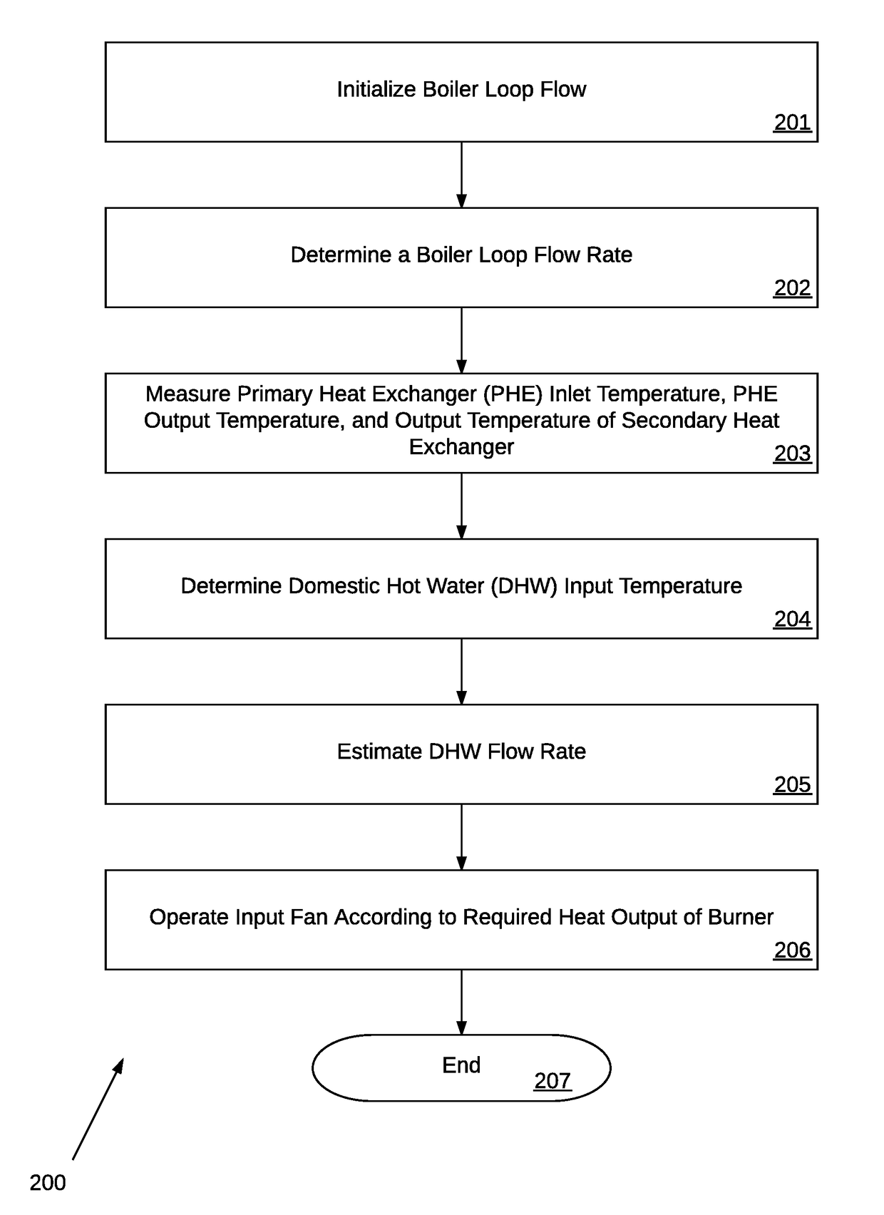
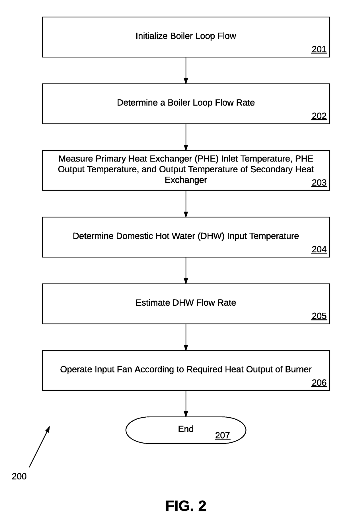
[0020]Various embodiments disclosed herein are directed to methods and systems for demand-based initialization of a combination boiler. In the embodiments described herein, a domestic hot water (DHW) output temperature sensor may be used to detect a DHW output temperature of a combination boiler.

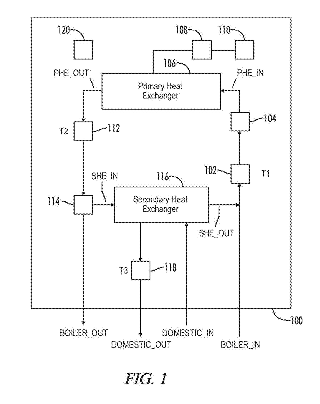
[0021]FIG. 1 illustrates a graphical block diagram illustrating a combination boiler consistent with an exemplary embodiment. The combination boiler 100 is configured to control operations associated with two water loops. The first loop is a boiler loop connected to the combination boiler 100 at an input BOILER_IN of the combination boil...


PUM


Abstract

A combination boiler provides heated water to a boiler loop and heated domestic hot water (DHW) to a DHW loop. A primary heat exchanger is connected to the boiler loop. A burner provides heat to the primary heat exchanger and an input fan supplies a fuel and air mixture to the burner. A secondary heat exchanger transfers heat energy from the boiler loop to a domestic water loop. A controller determines a boiler loop flow rate. The controller measures an input temperature of the boiler loop, an output temperature of the boiler loop, and a DHW output temperature of the domestic water loop. The controller determines a DHW input temperature and estimates a DHW flow rate. The input fan speed is initiated or operated according to a required heat output of the burner corresponding to the DHW flow rate.

Description

[0001]A portion of the disclosure of this patent document contains material that is subject to copyright protection. The copyright owner has no objection to the reproduction of the patent document or the patent disclosure, as it appears in the U.S. Patent and Trademark Office patent file or records, but otherwise reserves all copyright rights whatsoever.CROSS-REFERENCES TO RELATED APPLICATIONS[0002]This application claims benefit of the following patent application(s) which is / are hereby incorporated by reference: NoneSTATEMENT REGARDING FEDERALLY SPONSORED RESEARCH OR DEVELOPMENT[0003]Not ApplicableREFERENCE TO SEQUENCE LISTING OR COMPUTER PROGRAM LISTING APPENDIX[0004]Not ApplicableBACKGROUND OF THE INVENTION[0005]The present invention relates generally to controlling burner fan control for a combination boiler. More particularly, the present invention relates to suitably initializing, modifying, or controlling the firing rate of an input fan of a combination boiler for a Domestic...

Claims


Application Information

Patent Timeline
Patent Type & Authority Applications(United States)
IPC IPC(8): F24D19/10F24D3/08
CPCF24D19/1069F24D2220/06F24D2220/042F24D3/08F24H9/2035F24H1/52F23N1/022F23N2233/06F23N2225/12F23N2225/19F23N1/102F24H15/414F24H15/238F24H15/174F24H15/35F24H15/215F24H15/219
Inventor GAGNE, CURTIS GEORGE
Owner LOCHINVAR
Why Eureka
Try Eureka