Integrated ultrasonic testing and cathodic protection measurement probe

a technology of ultrasonic testing and cathodic protection, applied in special purpose vessels, materials analysis using sonic/ultrasonic/infrasonic waves, instruments, etc., can solve the problems of time-consuming and costly readjusting of the probe to perform repeated cp and/or ut measurements, unsuitable work-class rovs for shallowness and limited access

Active Publication Date: 2018-03-15
SAUDI ARABIAN OIL CO
View PDF4 Cites 33 Cited by
  • Summary
  • Abstract
  • Description
  • Claims
  • Application Information

AI Technical Summary

Benefits of technology

[0006]In accordance with one aspect of the invention, embodiments of the integrated probe systems include an outer gimbal having a front surface and a rear surface, and an inner gimbal coupled to the outer gimbal to provide at least one degree of freedom. The inner gimbal can include a front surface defining a cavity therein, and the inner gimbal can be shaped to define one or more ingresses that pass crosswise between the front and rear surfaces of the inner gimbal. In some embodiments, the ingresses are defined by the inner gimbal to be indentations formed along a circumference of the inner gimbal. In other embodiments, the ingresses are defined by the inner gimbal to be apertures transversely formed through the inner gimbal. In one or more embodiments, the integrated probe system includes an articulated carrier having a first end integrally formed with the rear surface of the inner gimbal and a ball caster disposed at a second end, in which the ball caster couples to the outer gimbal to provide the at least one degree of freedom to the inner gimbal.
[0007]Continuing with this aspect of the invention, in one or more embodiments, the integrated probe system includes a sensor housing seated in the cavity of the inner gimbal. An ultrasonic probe is within the sensor housing, the ultrasonic probe having a transducer crystal and a flexible membrane arranged about the transducer crystal, and a couplant disposed within a gap between the flexible membrane and the transducer crystal. Further, one or more legs, which each have an electrically conductive tip and a subsea housing containing a reference electrode, extend longitudinally away from the outer gimbal via the one or more ingresses and are arranged about the ultrasonic probe, such that the one or more legs are passively adjustable in response to a force imparted when the one or more legs contact the underwater surface.
[0008]In accordance with another aspect of the invention, embodiments of the integrated probe system include an ultrasonic sensor body, an ultrasonic testing cable disposed at a first end of the ultrasonic sensor body, and an ultrasonic probe disposed at a second end of the ultrasonic sensor body. In one or more embodiments, the ultrasonic probe includes an ultrasonic element and a flexible membrane adjacently spaced about the ultrasonic sensor body to define a gap between the ultrasonic element and the flexible membrane, in which the gap is filled with a couplant. Further, the integrated probe system can include a housing that defines an aperture therethrough, in which the aperture is centrally located in the housing and in which the ultrasonic probe is seated in the aperture, and the housing further including an electrically conductive portion. Additionally, the integrated probe system includes conductive leads connected to and extending from the electrically conductive portion.
[0009]In accordance with a further aspect of the invention, embodiments of a system for performing cathodic protection voltage readings and ultrasonic testing thickness measurements at an underwater surface substantially simultaneously are provided. The system includes a remotely operated underwater vehicle having a measuring arm, with an end effector disposed at a free end of the measuring arm. Additionally, the system includes an integrated probe for measuring cathodic protection voltage and ultrasonic testing thickness measurement coupled to the end effector. In one or more embodiments, the integrated probe includes an outer gimbal having a front surface and a rear surface, and an inner gimbal coupled to the outer gimbal to provide at least one degree of freedom. The inner gimbal has a front surface that defines a cavity therein, and the inner gimbal is shaped to define one or more ingresses that pass crosswise between the front and rear surfaces of the inner gimbal. The integrated probe further includes a sensor housing seated in the cavity of the inner gimbal, and an ultrasonic probe disposed within the sensor housing, in which the ultrasonic probe includes a flexible membrane arranged about a transducer crystal such that a gap is defined therebetween and filled with a couplant. Further, a voltage electrode is communicatively coupled to a reference electrode, in which the voltage electrode is disposed at the end effector or the integrated probe, and the reference electrode is disposed within the remotely operated underwater vehicle.
[0010]In accordance with an additional aspect of the invention, embodiments of a method of performing cathodic protection voltage readings and ultrasonic testing thickness measurements on an underwater surface with an integrated probe having an ultrasonic probe and at least one leg with an electrically conductive tip are provided. The method includes positioning a remotely operated vehicle, which has at least one robotic arm with an arm end effector disposed at a free end of the robotic arm and the integrated probe coupled to the arm end effector, in proximity to the underwater surface. The method then includes contacting the underwater surface with the integrated probe and orienting the integrated probe transverse to the underwater surface such that the ultrasonic probe and the at least one leg with an electrically conductive tip contacts the underwater surface. Then, the method continues by measuring, by the at least one leg, a voltage at the underwater surface, and measuring, by the ultrasonic probe, a thickness of the underwater surface. Further, in one or more embodiments, the method then includes processing, by a signal conditioner housed within the remotely operated vehicle, the voltage and the thickness of the underwater surface to produce a data file. The method continues by transmitting the data file to a data acquisition unit housed within the remotely operated vehicle. Additionally, the method includes processing, by the data acquisition unit, the data file to record, review, or analyze the voltage and thickness of the underwater surface.
[0011]In accordance with a still further aspect of the invention, embodiments of the integrated probe systems include a probe carrier that has at least one degree of freedom relative to a static base, and a rear surface coupled to the static base and a front surface having an electrically conductive portion and defining a cavity therein. Further, the electrically conductive portion can include one or more legs arranged about the ultrasonic probe, each leg having an electrically conductive tip and a subsea housing containing a reference electrode, and which extend longitudinally away from the probe carrier, in which the one or more legs are passively adjustable in response to a force imparted when the one or more legs contact the underwater surface. In one or more embodiments, the integrated probe systems include a sensor housing seated in the cavity of the probe carrier and an ultrasonic probe disposed within the sensor housing, the ultrasonic probe having a transducer crystal and a flexible membrane arranged about the transducer crystal, and a couplant disposed within a gap between the flexible membrane and the transducer crystal.

Problems solved by technology

In either case, due to load and logistical limitations inherent with conventional ROVs, CP and UT measurements are performed by two probes at separate ROV robotic arms or by exchanging one probe for another at a single arm.
In either case, the switching or readjusting of probes to perform repeated CP and / or UT measurements is time consuming and costly.
Additionally, due to the weight of conventional CP and UT probe systems and the need for a two-armed ROV system, only larger Work-Class ROVs are capable of attaching two arms to alternatingly perform both measurements in a single trip.
However, Work-Class ROVs are unsuitable for shallow and limited accessibility (e.g., surfaces within small cavities) inspection sites.

Method used


Image

  • Integrated ultrasonic testing and cathodic protection measurement probe
  • Integrated ultrasonic testing and cathodic protection measurement probe
  • Integrated ultrasonic testing and cathodic protection measurement probe

Examples


Embodiment Construction

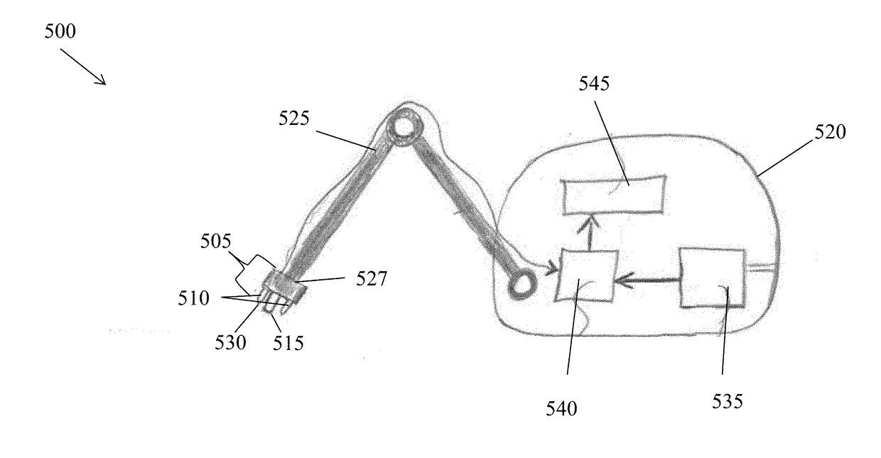
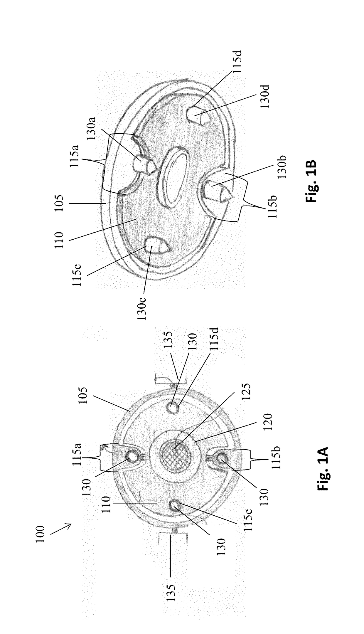
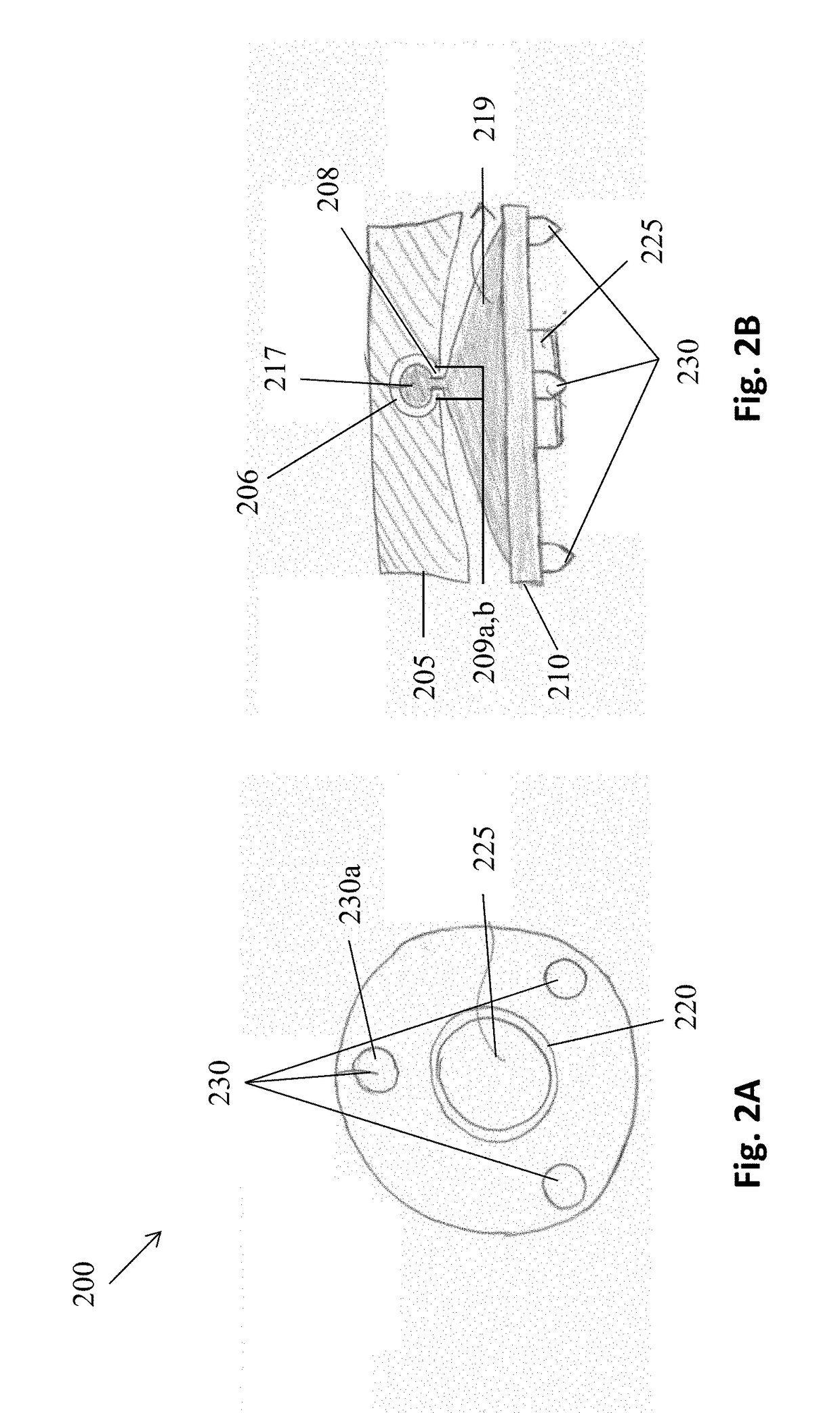
[0021]The invention is now described with reference to the accompanying drawings, which form a part hereof, and which show, by way of illustration, example implementations and / or embodiments of the present invention. It is to be understood that other embodiments can be implemented and structural changes can be made without departing from the spirit of the present invention. Among other things, for example, the disclosed subject matter can be embodied as methods, devices, components, or systems.

[0022]Furthermore, it is recognized that terms may have nuanced meanings that are suggested or implied in context beyond an explicitly stated meaning. Likewise, the phrase “in one embodiment” as used herein does not necessarily refer to the same embodiment and the phrase “in another embodiment” as used herein does not necessarily refer to a different embodiment. It is intended, for example, that claimed subject matter can be based upon combinations of individual example embodiments, or combina...


PUM

PropertyMeasurementUnit
frequenciesaaaaaaaaaa

Abstract

This application discloses integrated probes and probe systems, which can be attached to the robotic arms of a remotely operated vehicle to perform both cathodic protection (CP) voltage measurements and ultrasonic testing (UT) thickness measurements at an underwater surface. In some embodiments, the integrated probe system couples an inner and outer gimbal together such that one or more electrically conductive legs pass from the outer gimbal through the inner gimbal. These legs are arranged about an ultrasonic sensor which extends from the front surface of the inner gimbal. When the integrated probe contacts the underwater surface, both the ultrasonic sensor and at least one leg contact the surface, thereby providing substantially simultaneous CP and UT measurements.

Description

CROSS-REFERENCE TO RELATED APPLICATIONS[0001]This application claims priority under 35 U.S.C. § 119 to U.S. Provisional Application Ser. No. 62 / 395,162, filed Sep. 15, 2016, which is hereby incorporated by reference in its entirety.FIELD OF THE INVENTION[0002]This patent application generally relates to testing and measuring mechanisms, and more particularly to probe systems for ultrasonically measuring thickness and performing cathodic protection voltage readings in an underwater environment.BACKGROUND[0003]In order to non-destructively measure the thickness of a structure, one common practice is to have a measuring device emit ultrasonic waves at the surface of the structure and to measure the time it takes for the ultrasonic wave to return to the measuring device. Ultrasonic testing (“UT”) is applicable for measuring the thickness of metal structures, such as underwater structures like boat hulls, pilings, pipelines, and risers. In order to limit corrosive effects to such underwa...

Claims


Application Information

Patent Timeline
Patent Type & Authority Applications(United States)
IPC IPC(8): G01N17/02G01B17/02G01R19/00G01N29/22G01N29/265G01N29/24C23F13/04
CPCG01N17/02G01B17/025G01R19/0092G01N29/226G01N2291/101G01N29/245C23F13/04G01N2291/0231G01N2291/02854G01N29/265G01B17/02G01N29/225C23F2213/31G01N29/043G01N2291/0234B63G8/001B63G2008/005C23F13/22
Inventor ABDELLATIF, FADLAL-SAIARI, HAMADOUTA, ALIAMER, AYMANPATEL, SAHEJADOBEDAN, AMEENTRIGUI, HASSANE
Owner SAUDI ARABIAN OIL CO
Why Eureka
Try Eureka