Supercharge Your Innovation With Domain-Expert AI Agents!

Voltage conversion module and bobbin

a voltage conversion module and bobbin technology, applied in the direction of electric variable regulation, process and machine control, instruments, etc., can solve the problems of large power loss of the power conversion system having the diode or schottky diode to rectify power, and large power loss during the electronic device under light load condition

Active Publication Date: 2018-03-15
CHICONY POWER TECH CO LTD
View PDF0 Cites 1 Cited by
  • Summary
  • Abstract
  • Description
  • Claims
  • Application Information

AI Technical Summary

Benefits of technology

The solution effectively reduces power loss during light load conditions and improves efficiency by selectively placing synchronous rectifying units in conducting states and controlling the coupling distance between primary and secondary windings, ensuring efficient power delivery and heat management.

Problems solved by technology

Since diode and Schottky diode have designated forward bias, the power loss of the power conversion system having the diode or Schottky diode to rectify power is large.
Specifically, when an electronic device electrically connected to the power conversion system is activated, the synchronous rectifiers perform synchronous rectifying procedure, and the MOSFETs of the synchronous rectifiers are switched to rectify the power entering the synchronous rectifiers; however, when the electronic device is inactivated, the synchronous rectifiers does not perform synchronous rectifying procedure.
Even if the operation manner of the synchronous rectifier mentioned above is easy, the power provides by the power conversion system is a constant no matter the electronic device during non-light load condition and light load condition, thus the power loss during the electronic device under light load condition is large.

Method used


Image

  • Voltage conversion module and bobbin
  • Voltage conversion module and bobbin
  • Voltage conversion module and bobbin

Examples


first embodiment

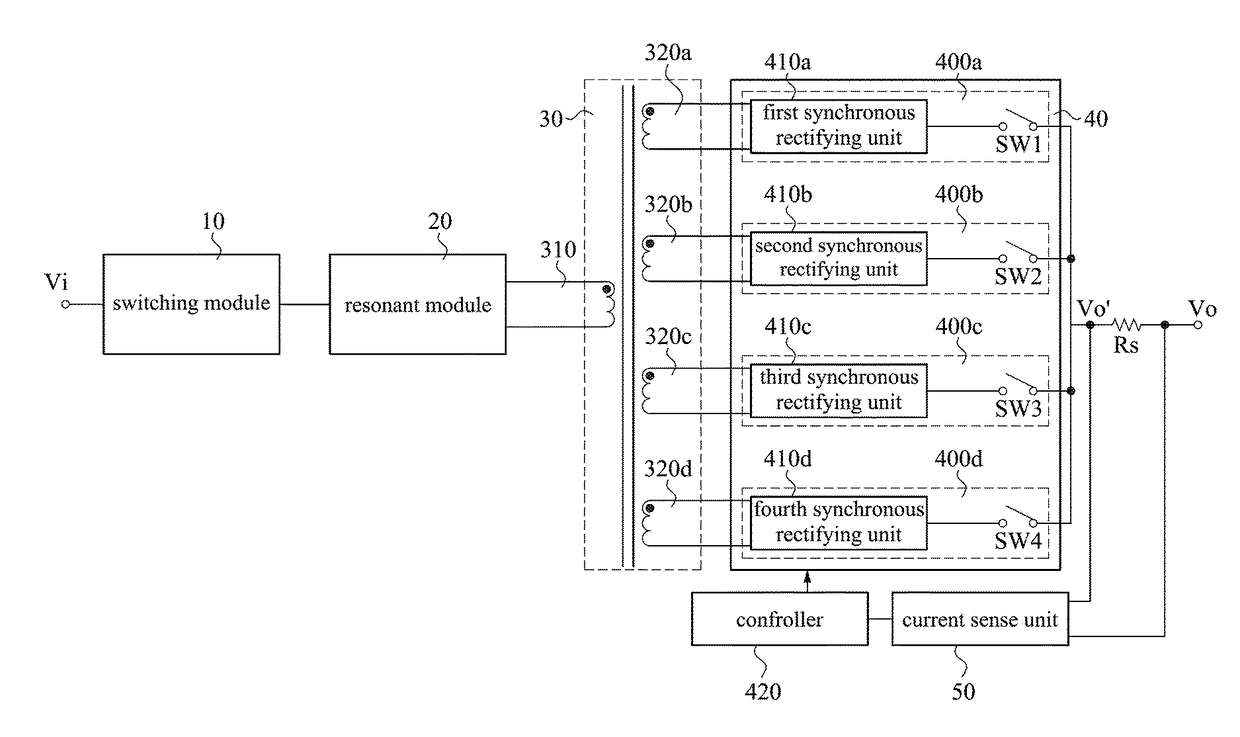
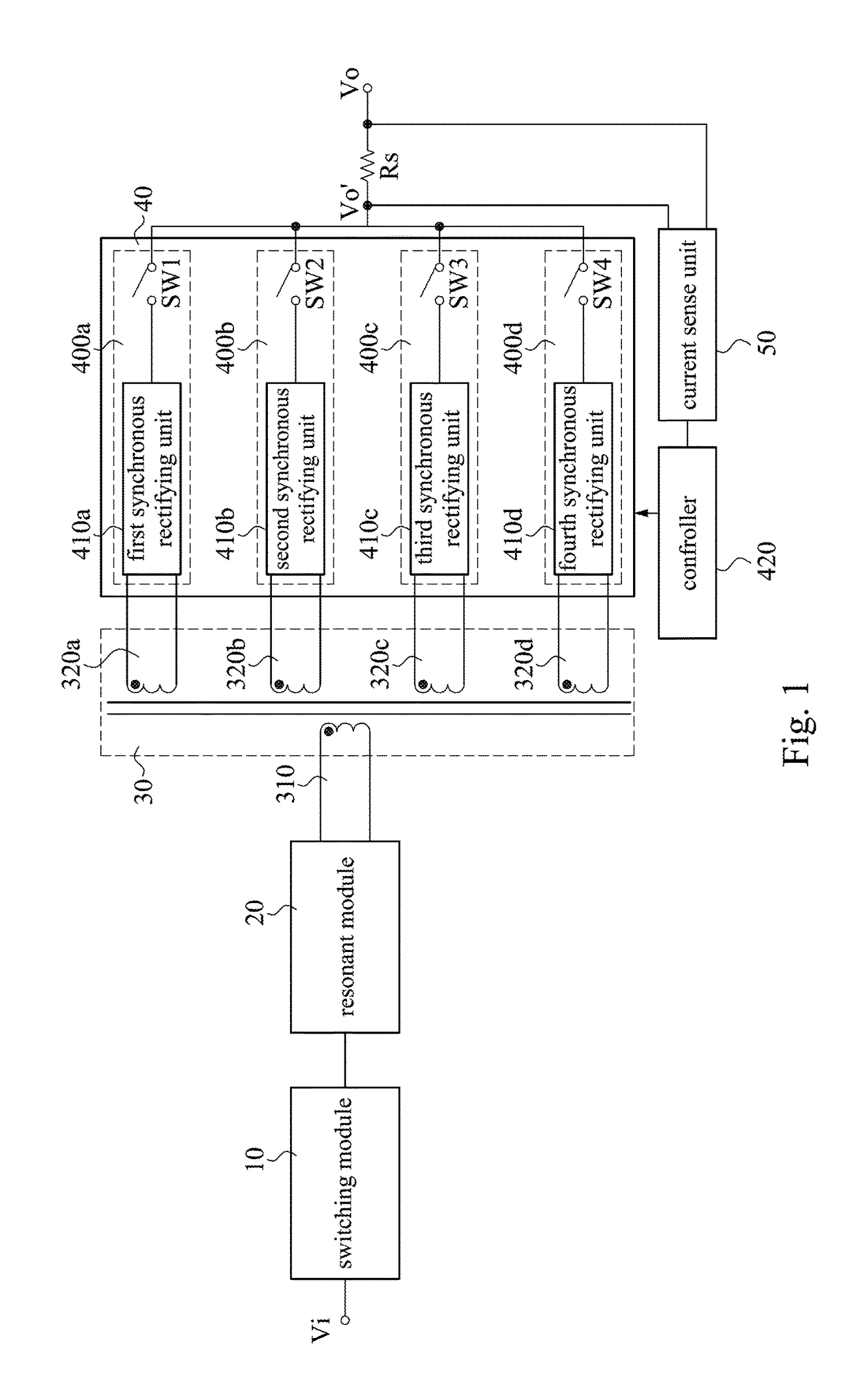
[0034]Reference is made to FIG. 1, which is a circuit block diagram of a power conversion system according to the present disclosure. In FIG. 1, the power conversion system (its reference numeral is omitted) receives an input voltage Vi and is configured to provide an output voltages Vo. The power conversion system includes a primary side and a secondary side, which are separated by an isolating transformer 30. The isolating transformer 30 includes a primary winding 310 and a plurality of secondary windings 320a˜320d magnetically coupled to the primary winding 310. The power conversion system further includes a switching module 10, a resonant module 20, an output-controlling device 40, and a current sense unit 50. The switching module 10, the resonant module 20, and the primary winding 310 are arranged at the primary side of the power conversion system, and the secondary windings 320a˜320d, the output-controlling device 40, and the current sense unit 50 are arranged at the secondary...

second embodiment

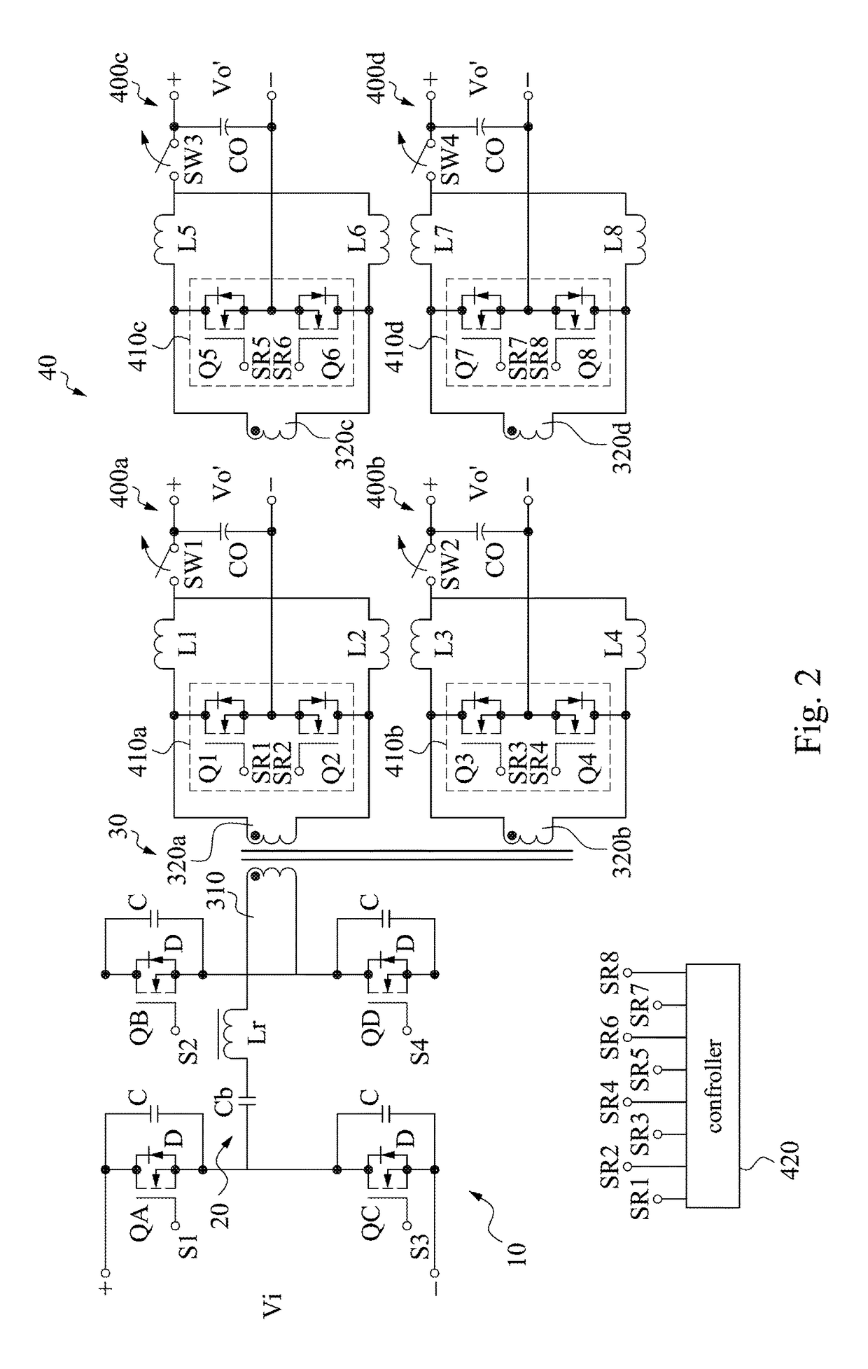
[0092]Reference is made to FIG. 11, which is a circuit diagram of a power conversion system according to the present disclosure. In FIG. 11, the power conversion system includes a switching module 10, a resonant module 20, a transformer 30, and an output-controlling device 40. The transformer 30 includes a primary winding 310 and a plurality of secondary windings 320a˜320d coupled with the primary winding 310.

[0093]The function and relative description of switching module 10 and the resonant module 20 of the power conversion system shown in the FIG. 11 are the same as that of first embodiment (shown in the FIG. 2) mentioned above and are not repeated here for brevity, and the switching module 10 and the resonant module 20 of the power conversion system shown in the FIG. 11 can achieve the functions as power conversion system of the first embodiment does. It should be noted that the transformer 30 and the output-controlling device 40 shown in the FIG. 11 is different from that of the...


PUM


Abstract

The present disclosure is related to a voltage conversion module which includes a front side magneto-sensitive unit, at least one voltage conversion unit, a core group, and a bobbin. The bobbin includes a first accommodating part, a second accommodating part, and a through hole. The first accommodating part is used for accommodating the front side magneto-sensitive unit. The second accommodating part is used for accommodating the at least one voltage conversion unit. The through hole is used for accommodating the core group. The second accommodating part includes first and second openings. The first opening is disposed at one side of the second accommodating part. The second opening is disposed at another side of the second accommodating part. The first and second openings are disposed opposite to each other, and a heat dissipation channel is formed between the first opening, the second opening and the at least one voltage conversion unit.

Description

CROSS-REFERENCE TO RELATED APPLICATIONS[0001]This application is a continuation-in-part of U.S. application Ser. No. 15 / 704,007, filed Sep. 14, 2017, which is a reissue application of U.S. Pat. No. 9,559,609 B2, issued Jan. 31, 2017, which are herein incorporated by reference in their entireties. This application is a continuation-in-part of U.S. application Ser. No. 15 / 073,319, filed Mar. 17, 2016, which claims priority to Taiwan Application Serial Number 104133388, filed Oct. 12, 2015, which are herein incorporated by reference in their entireties. This application claims priority to Provisional Application No. 62 / 466,383, filed Mar. 3, 2017, which is incorporated by reference herein in its entirety. The present application is a continuation application of U.S. application Ser. No. 15 / 706,785, filed Sep. 18, 2017, which is herein incorporated by reference. All of these applications are incorporated herein by reference.BACKGROUNDField of Invention[0002]The present invention relates...

Claims


Application Information

Patent Timeline
Patent Type & Authority Applications(United States)
IPC IPC(8): H02M3/335
CPCH02M3/33592H02M3/285H01F27/2804H01F27/40H01F2027/2819H02M7/003Y02B70/10H02M1/0058H02M1/009H02M7/08H02M1/14H02M3/28
Inventor HSIAO, YUNG-HUNGYEN, CHIA-HSIENYIN, LIEH-CHUNGHSIAO, CHENG-CHANGHSU, HAO-TE
Owner CHICONY POWER TECH CO LTD
Features
  • R&D
  • Intellectual Property
  • Life Sciences
  • Materials
  • Tech Scout
  • Unparalleled Data Quality
  • Higher Quality Content
  • 60% Fewer Hallucinations
Learn More