Non-contact vital sign monitoring system

a vital sign and non-contact technology, applied in the field of non-contact vital sign monitoring system, can solve the problems of system configuration limitations, subject to feel uncomfortable during monitoring, and doppler shift affecting the vital sign monitoring

Active Publication Date: 2018-03-22
NAT SUN YAT SEN UNIV
View PDF2 Cites 7 Cited by
  • Summary
  • Abstract
  • Description
  • Claims
  • Application Information

AI Technical Summary

Benefits of technology

[0006]The primary object of the non-contact vital sign monitoring system of the present invention is to configure two radar devices at the same side of a biological subject to transmit wireless signals to the subject and receive the reflected signals from the subject via two different gain antennas for detecting Doppler shift in which the components due to body movement are approximately equal in ma...

Problems solved by technology

The contact type vital sign monitoring system has to contact the subject's skin for a long time for accurate detection of the subject's vital signs, and the subject's moving range may be limited by the wires connected to the contact type vital sign monitoring system, causing the subject to feel uncomfortable during monitoring.
However, the reflected signals caused by body movement of the subject will also cause Doppler shift to affect the vital sign monitoring.
However, the system is limited in configuration because the two CW radar apparatuses have to configure at opposite sides of the subject.
The subject's vital signs are therefore difficult...

Method used


Image

  • Non-contact vital sign monitoring system
  • Non-contact vital sign monitoring system
  • Non-contact vital sign monitoring system

Examples


first embodiment

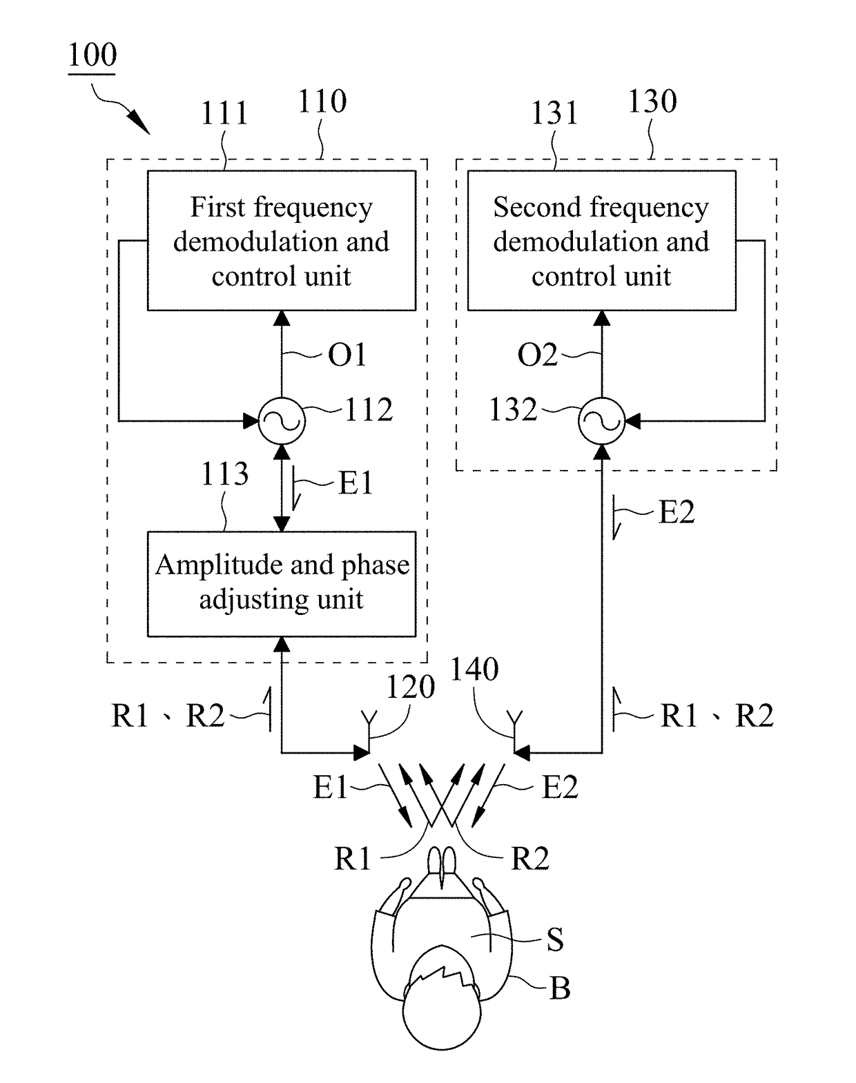
[0017]With reference to FIG. 1, a non-contact vital sign monitoring system 100 in accordance with the present invention comprises a first radar device 110, a first antenna 120, a second radar device 130 and a second antenna 140.

[0018]With reference to FIG. 1, the first radar device 110 includes a first frequency demodulation and control unit 111, a first voltage-controlled oscillator (VCO) 112 and an amplitude and phase adjusting unit 113, wherein the first VCO 112 is electrically connected with the first frequency demodulation and control unit 111 and the amplitude and phase adjusting unit 113. The first frequency demodulation and control unit 111 is used for controlling the frequency of a first transmission signal E1 generated from the first VCO 112 and demodulating an output signal O1 from the first VCO 112, wherein the first transmission signal E1 is delivered to the amplitude and phase adjusting unit 113, and the amplitude and phase adjusting unit 113 is used for adjusting the ...

second embodiment

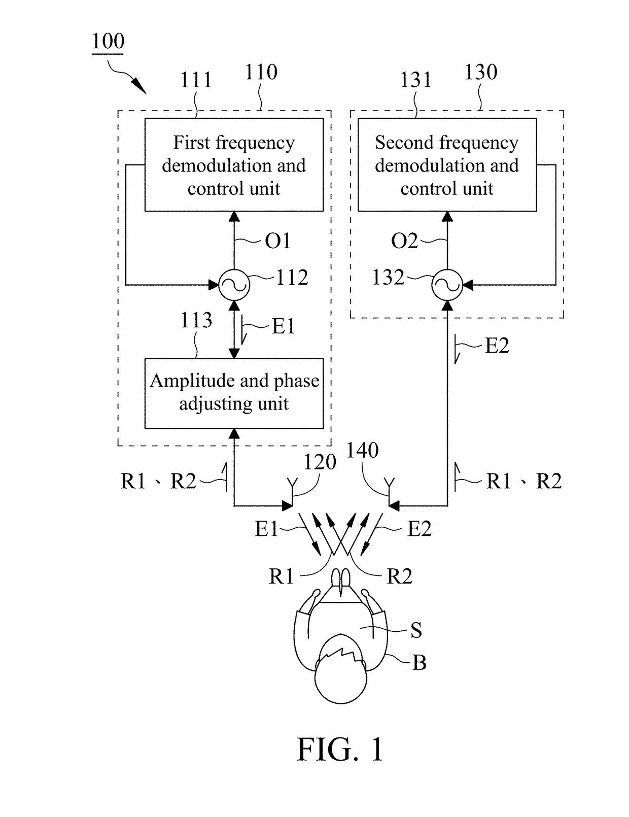
[0027]With reference to FIG. 2, the first antenna 120 and the second antenna 140 in the present invention are setup in an up-down configuration, wherein the first antenna 120 has a first central axis 121 and the second antenna 140 has a second central axis 141, and the first central axis 121 and the second central axis 141 both are directed to an area A on the side S of the biological subject B. The second central axis 141 is parallel to floor substantially, and the first central axis 121 is tilted relative to floor to form an included angle θ of less than 90 degrees between the first central axis 121 and the second central axis 141. In this embodiment, the included angle θ is 55 degrees when the system operates in the 2.4 GHz industrial, scientific and medical band.

[0028]Owing to the gain of the first antenna 120 is higher than that of the second antenna 140 in this embodiment, the magnitude of the first reflected signal R1 received by the first antenna 120 will be higher than that...

third embodiment

[0030]With reference to FIG. 5, the first antenna 120 and the second antenna 140 in the present invention are setup in a front-rear configuration, wherein the first antenna 120 has a first central axis 121 and the second antenna 140 has a second central axis 141, and the first central axis 121 and the second central axis 141 both are directed to an area A on the side S of the biological subject B. There is a distance D between the first antenna 120 and the second antenna 140, and the second antenna 140 is located between the first antenna 120 and the biological subject B. In this embodiment, the distance D is 20 cm when the system operates in the 2.4 GHz industrial, scientific and medical band.

[0031]In the setup of the first antenna 120 and the second antenna 140 of the third embodiment, the first transmission signal E1 transmitted from the first antenna 120 is partially blocked by the metal plate of the second antenna 140 to decrease the Doppler component of the first reflected sig...


PUM


Abstract

A non-contact vital sign monitoring system transmits wireless signals to the same side of a biological subject via two antennas with different gains, and the two antennas receive two reflected signals from the biological subject with random body movement. Under a proper setup of the two antennas, the two reflected signals can be adjusted by an amplitude and phase adjusting unit to have the Doppler shift components caused by body movement with equal magnitude and out of phase and the Doppler shift components caused by vital signs with different magnitude. Therefore, the random body movement effect can be cancelled based on the relation between the two reflected signals in using the system to monitor the vital signs of the subject.

Description

FIELD OF THE INVENTION[0001]This invention generally relates to a non-contact vital sign monitoring system, and more particularly to a non-contact vital sign monitoring system able to cancel the random body movement effect.BACKGROUND OF THE INVENTION[0002]Vital sign monitoring system, extensively applied to healthcare and fitness equipment, can track health and exercise of a biological subject by capturing and analyzing the changes in vital signs.[0003]In general, there are two types of conventional vital sign monitoring system, contact type and non-contact type. The contact type vital sign monitoring system has to contact the subject's skin for a long time for accurate detection of the subject's vital signs, and the subject's moving range may be limited by the wires connected to the contact type vital sign monitoring system, causing the subject to feel uncomfortable during monitoring. In contrast, the non-contact vital sign monitoring system transmits wireless signals to the subjec...

Claims


Application Information

Patent Timeline
IPC IPC(8): A61B5/05A61B5/00
CPCA61B5/7228A61B5/05A61B5/0002A61B5/0205A61B5/024A61B5/0507A61B5/0816A61B5/7214A61B5/7225A61B5/7278A61B2562/0228A61B2562/04G01S7/034G01S7/354G01S7/40G01S13/34G01S13/536G01S13/87G01S13/88
Inventor HORNG, TZYY-SHENGTANG, MU-CYUNKUO, CHAO-YUN
Owner NAT SUN YAT SEN UNIV
Why Eureka
Try Eureka