Support structure constrained topology optimization for additive manufacturing

Active Publication Date: 2018-03-22
WISCONSIN ALUMNI RES FOUND
View PDF0 Cites 30 Cited by
  • Summary
  • Abstract
  • Description
  • Claims
  • Application Information

AI Technical Summary

Benefits of technology

[0010]The present invention overcomes the aforementioned drawbacks by providing systems and processes for additive manufacturing using a topology optimization (TO) framework that generates designs that have significantly reduced suppor

Problems solved by technology

However, structures built with AM must observe certain limitations of the AM processes.
Polymer AM processes work with melted, partially melted, and/or amorphous materials, and unsolidified portions of layers can droop or creep where there is no underlying material providing support.
The same “overhanging” portions can be damaged by burning during metal AM processes.
Support structures directly add to the build-time and material cost.
Further, support structures can be hard to remove (and sometimes even inaccessible), leading to the post-fabrication (clean-up) cost.
Designs stemming from TO are geometrically complex, and therefore hard to manufacture using traditional processes, but these desi

Method used


Image

  • Support structure constrained topology optimization for additive manufacturing
  • Support structure constrained topology optimization for additive manufacturing
  • Support structure constrained topology optimization for additive manufacturing

Examples


numerical examples

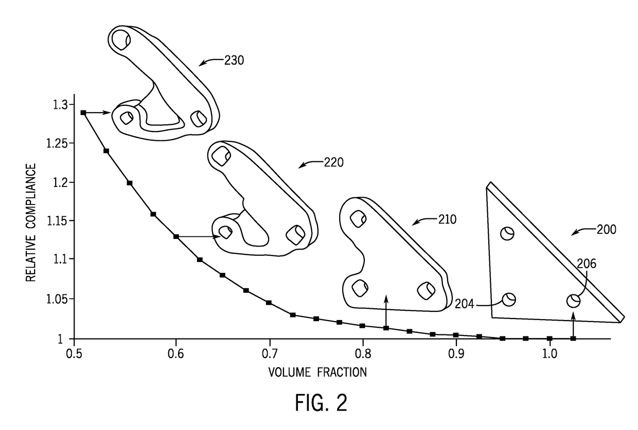
[0082]Several examples are now described to demonstrate the proposed TO framework and optimization methods. In all of the examples, the material is assumed to be isotropic ABS plastic with Young's modulus of E=2 GPa and Poisson ratio of ν=0.39. The interior support sensitivity is included in all of the examples to achieve a smoother sensitivity field.

[0083]FIG. 10A illustrates an exemplary 2D Messerschmidt-Bölkow-Blohm (MBB) beam 1000, an object common to TO examples. The threshold angle is assumed to be 3π / 4. The initial design requires no support and the objective is to find the stiffest design at 0.65 volume fraction. FIG. 10B illustrates an unconstrained optimization 1010 performed without support volume constraints; the optimization 1010 presents a relative compliance of 1.29 (i.e., 129% of the initial MBB beam 1000), and its support volume is the baseline support volume against which the optimizations created by the present methods are compared.

[0084]FIGS. 10C-E illustrate opt...


PUM

PropertyMeasurementUnit
Angleaaaaaaaaaa
Volumeaaaaaaaaaa
Sensitivityaaaaaaaaaa

Abstract

Systems and methods for generating designs of objects for additive manufacturing (AM) include a topological optimization framework that facilitates optimized computer generated designs requiring significantly reduced support structures. Towards this end, the concept of ‘support structure topological sensitivity’ is introduced. This is combined with performance sensitivity to result in a TO framework that maximizes performance, subject to support structure constraints. The robustness and efficiency of the proposed method is demonstrated through numerical experiments, and validated through fused deposition modeling, a popular AM process.

Description

STATEMENT REGARDING FEDERALLY SPONSORED RESEARCH[0001]This invention was made with government support under 1500205 awarded by the National Science Foundation. The government has certain rights in the invention.BACKGROUND OF THE INVENTION[0002]This disclosure relates generally to methods of optimizing designs, and more specifically to methods for designing structures that are optimized for manufacture with additive manufacturing processes.[0003]Additive manufacturing (AM) processes are processes for fabricating parts through material addition. Specifically, AM devices manufacture three-dimensional objects by adding layer-upon-layer of material in the “build direction” (e.g., from the bottom to the top of the object). The growing interest in AM stems from its ability to fabricate highly complex parts with relative ease. However, structures built with AM must observe certain limitations of the AM processes. Polymer AM processes work with melted, partially melted, and / or amorphous mate...

Claims


Application Information

Patent Timeline
IPC IPC(8): B29C67/00B33Y10/00B33Y50/00G05B17/02
CPCB29C67/0088B29C67/0092B33Y10/00G05B2219/49023G05B17/02B29C67/0055B33Y50/00B29C64/386B29C64/40
Inventor SURESH, KRISHNANMIRZENDEHDEL, AMIRMASSOUD
Owner WISCONSIN ALUMNI RES FOUND
Why Eureka
Try Eureka