
Collision detection device for vehicle

a detection device and vehicle technology, applied in vehicle components, pedestrian/occupant safety arrangements, bumpers, etc., can solve the problems of tube components that cannot be fully deformed at a time, and the output of pressure sensors may become small, so as to achieve high accuracy

Active Publication Date: 2018-03-22
DENSO CORP
View PDF0 Cites 6 Cited by
  • Summary
  • Abstract
  • Description
  • Claims
  • Application Information

AI Technical Summary

Benefits of technology

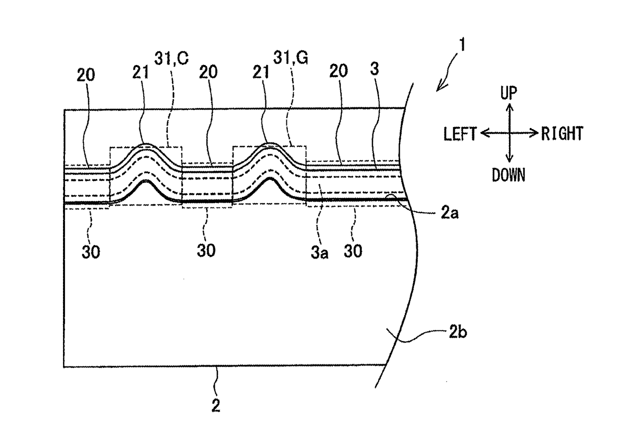
The invention is a collision detection device for vehicles that can detect collisions with pedestrians or other objects in front of the vehicle. The device includes a detection tube component that is designed to fully deform during a collision, in order to ensure accurate detection. The detection tube component is mounted in a groove portion in the vehicle bumper and has curved surfaces that increase the area of contact with the collision object, resulting in a larger deformation of the detection tube component and improved output from the pressure sensor. This ensures consistent and accurate detection of collisions, regardless of their position in the vehicle.

Problems solved by technology

However, in the collision detection device for a vehicle, for example, if the impact generated by the collision with the pedestrian on the front side of the vehicle is released to the lateral side of the vehicle, the tube component may not fully be deformed at a time of the collision, at a corner portion of the bumper cover adjacent to the end in the vehicle width direction, which is inclined to the front-rear direction of the vehicle.
Moreover, the tube component may not fully be deformed at a high rigidity part where the rigidity of the bumper cover or a component in the bumper is relatively high, because a load applied to the tube component becomes small at a time of the collision.
In such a case, the output of the pressure sensor may become small when a pedestrian collides, and it may be difficult to secure the required output.

Method used


Image

  • Collision detection device for vehicle
  • Collision detection device for vehicle
  • Collision detection device for vehicle

Examples


first embodiment

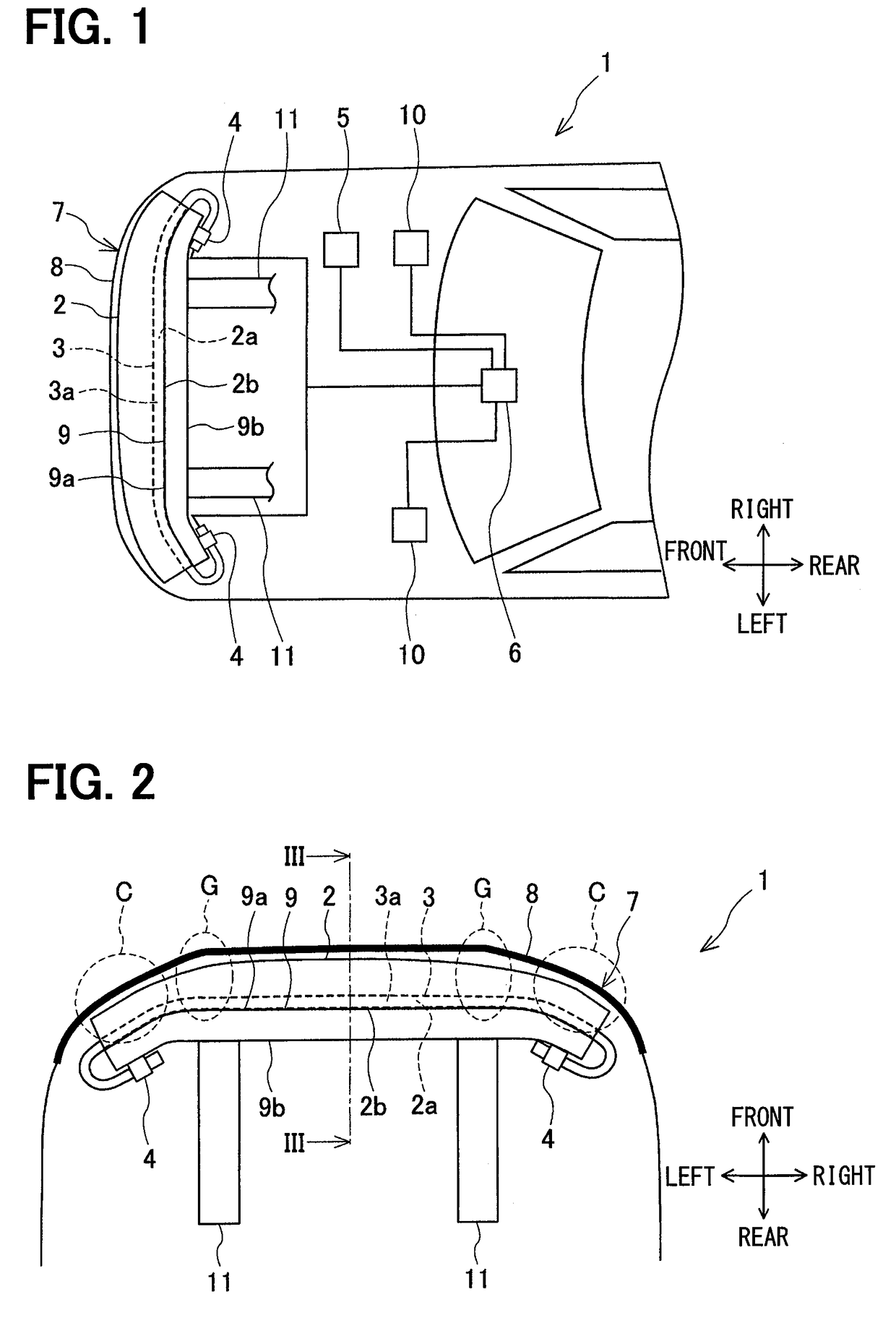
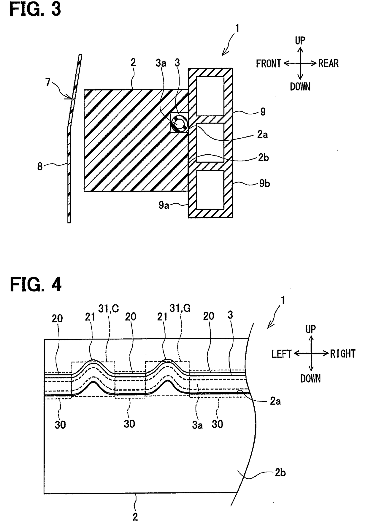
[0022]A collision detection device for a vehicle according to a first embodiment is explained with reference to FIG. 1 to FIG. 7. As shown in FIG. 1 and FIG. 2, the collision detection device 1 of this embodiment includes a bumper absorber 2, a hollow detection tube component 3, a pressure sensor 4, a speed sensor 5, and a collision detection ECU 6. The collision detection device 1 detects a collision of an object (such as pedestrian) to a bumper 7 disposed at the front of the vehicle. As shown in FIG. 3, the bumper 7 mainly includes a bumper cover 8 and a bumper reinforcement 9 in addition to the bumper absorber 2.

[0023]The bumper absorber 2 absorbs impact in the bumper 7, and is made of, for example, polypropylene foam. As shown in FIG. 3, the bumper absorber 2 is disposed at a position opposing a front surface 9a of the bumper reinforcement 9, e.g., on the front of the vehicle, and extends in the vehicle width direction. Although not illustrated, the bumper absorber 2 and the bum...

second embodiment

[0061]A second embodiment is described with reference to FIG. 8. In FIG. 8, the same mark is given to the same portion as the first embodiment to omit the explanation, and only a different portion is explained. In the second embodiment, as shown in FIG. 8, the detection tube component 3 is mounted in the groove portion 2a in the state where a cove curve portion 32 of the detection tube component 3 is curved to the lower side relative to the horizontal portion 30. The groove portion 2a has the horizontal groove portion 20 extending in the vehicle horizontal direction, and the curve groove portion 22 curved to the lower side relative to the horizontal groove portion 20.

[0062]Similarly to the first embodiment, the curve groove portion 22 is defined at totally four places, e.g., two of the high rigidity parts G right and left where the rigidity of the front grille is high and two of the corner parts C right and left of the bumper cover 8, and is formed to be curved to the lower side rel...

third embodiment

[0065]A third embodiment is described with reference to FIG. 9. In FIG. 9, the same mark is given to the same portion as the first embodiment to omit the explanation, and only a different portion is explained. In the third embodiment, as shown in FIG. 9, the groove portion 2a has the horizontal groove portion 20 extending in the vehicle horizontal direction, and a curve groove portion 23 curved to the upper side and the lower side relative to the horizontal groove portion 20 to have wave shape. The detection tube component 3 is mounted in the groove portion 2a in a state where the detection tube component 3 has the horizontal portion 30 extending in the vehicle horizontal direction and the cove curve portion 33 curved to the upper side and the lower side relative to the horizontal portion 30.

[0066]Specifically, the curve groove portion 23 is formed to be curved in the wave shape from the corner part C adjacent to the end in the vehicle width direction to the high rigidity part G whe...


PUM


Abstract

A collision detection device for a vehicle includes: a bumper absorber disposed on a front side of a bumper reinforcement in a bumper of the vehicle; a detection tube component mounted in a groove portion defined in the bumper absorber to extend in a width direction of the vehicle, a hollow part being defined in the detection tube component; and a pressure sensor that detects a pressure in the hollow part of the detection tube component, and detects a collision of an object to the bumper based on a pressure detection result by the pressure sensor. The detection tube component is mounted in the groove portion in a state where the detection tube component has at least one or more cove curve portions curved in an up-down direction of the vehicle.

Description

CROSS REFERENCE TO RELATED APPLICATION[0001]This application is based on Japanese Patent Application No. 2015-80690 filed on Apr. 10, 2015, the disclosure of which is incorporated herein by reference.TECHNICAL FIELD[0002]The present disclosure relates to a collision detection device for a vehicle, which detects a collision with a pedestrian and the like.BACKGROUND ART[0003]Conventionally, a vehicle is equipped with a pedestrian protection device for reducing an impact to a pedestrian in case where the pedestrian collides with the vehicle. The vehicle has a collision detection device including a sensor that is disposed in a bumper of the vehicle. When the sensor detects that a pedestrian collides with the vehicle, the pedestrian protection device is operated to reduce the impact applied to the pedestrian. A pop-up hood is one of the pedestrian protection devices. When a collision is detected, the pop-up hood raises the back end of an engine hood so as to increase the interval between...

Claims


Application Information

Patent Timeline
Patent Type & Authority Applications(United States)
IPC IPC(8): B60R19/48B60R21/38B60R21/0136
CPCB60R19/483B60R21/38B60R21/0136B60R19/18B60R2019/186B60R21/00
Inventor NAKANE, DAISUKETANABE, TAKATOSHIYOSHIDA, TOMOKAZUAMANO, KOUTA
Owner DENSO CORP
Learn More