Electric Motor

Inactive Publication Date: 2018-03-22
JOHNSON ELECTRIC INTERNATIONAL AG
View PDF13 Cites 1 Cited by
  • Summary
  • Abstract
  • Description
  • Claims
  • Application Information

AI Technical Summary

Benefits of technology

[0024]The present methodology enables the assembly of an electric motor such that a fully electrically-functional unit is introduced directly into the

Problems solved by technology

Furthermore, the total number of components which are required to assemble the motor is reduced, as well as the number of connections required,

Method used


Image

  • Electric Motor
  • Electric Motor
  • Electric Motor

Examples


Example

[0029]The present invention will be further described below with reference to the accompanying drawings and the following embodiments.

DETAILED DESCRIPTION OF THE PREFERRED EMBODIMENTS

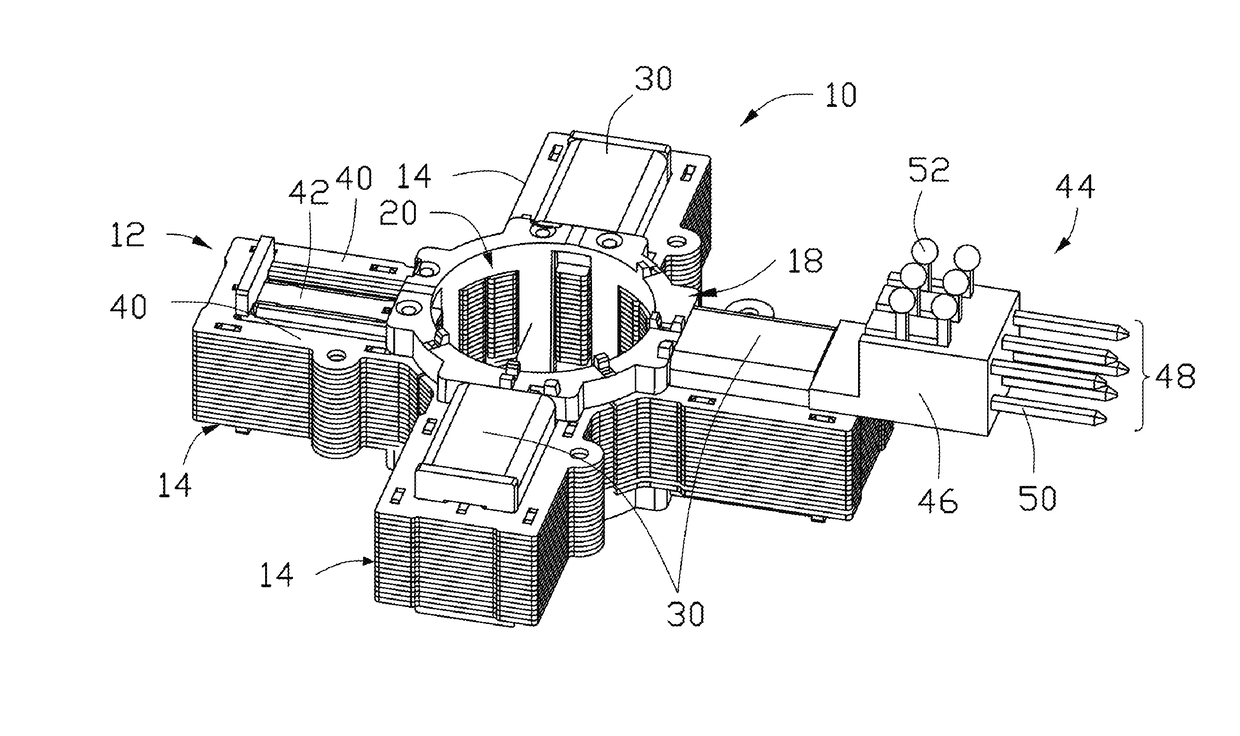
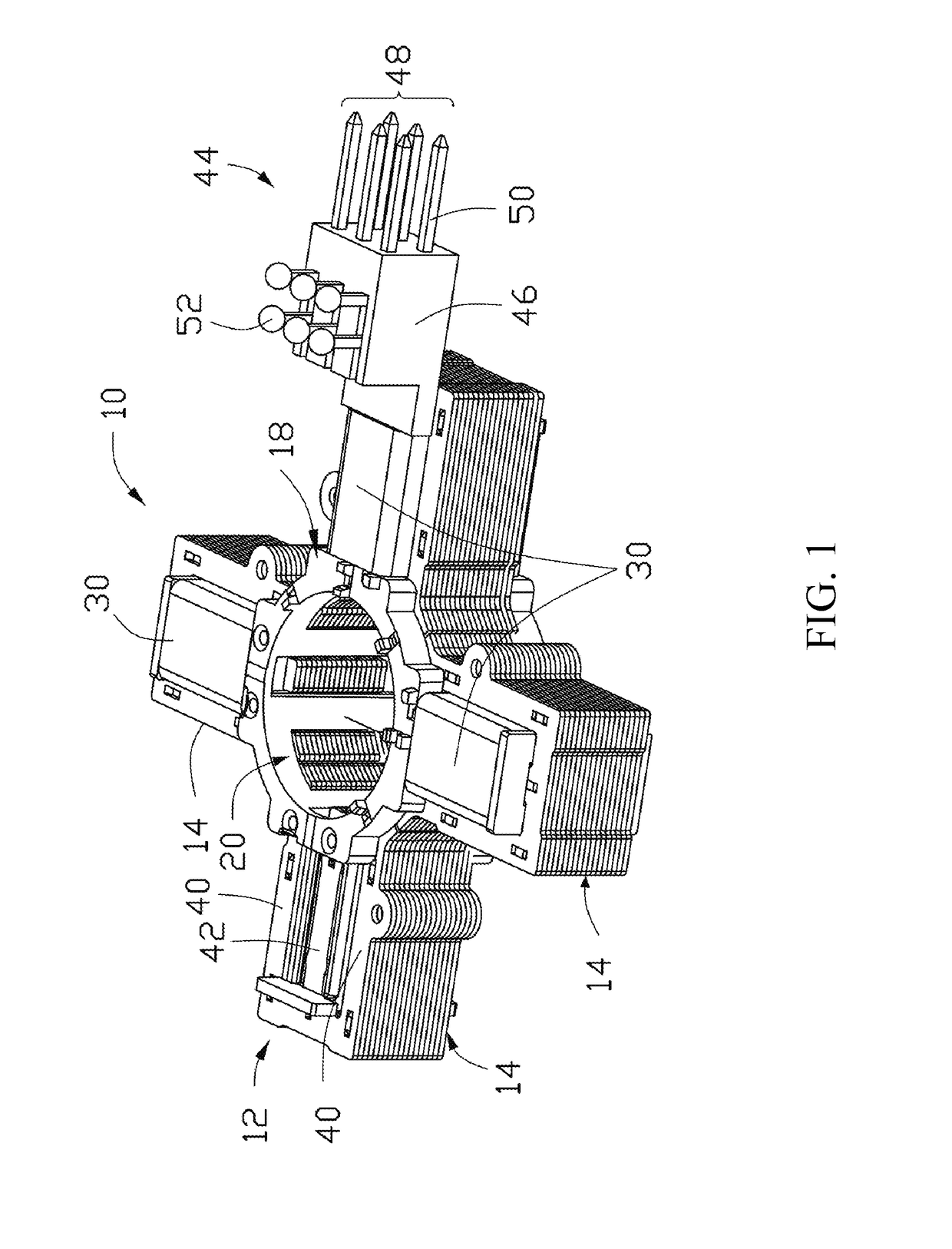
[0030]Referring firstly to FIG. 1, there is shown an electric motor, indicated globally at 10, and which is here formed as a star motor. The star motor includes a stator 12 and a rotor 16 rotatably mounted relative to the stator 12. The rotor 16 is omitted from FIG. 1 for clarity, but can be seen in FIG. 3. Whilst a star motor is used in the present embodiment, it will be apparent that the following invention could be utilised in a wide variety of electric motors, in particular for stepper motors, and may be particularly useful in the context of stepper actuators such as those used in heating, ventilation and air conditioning systems, for instance, those provided in motor vehicles.

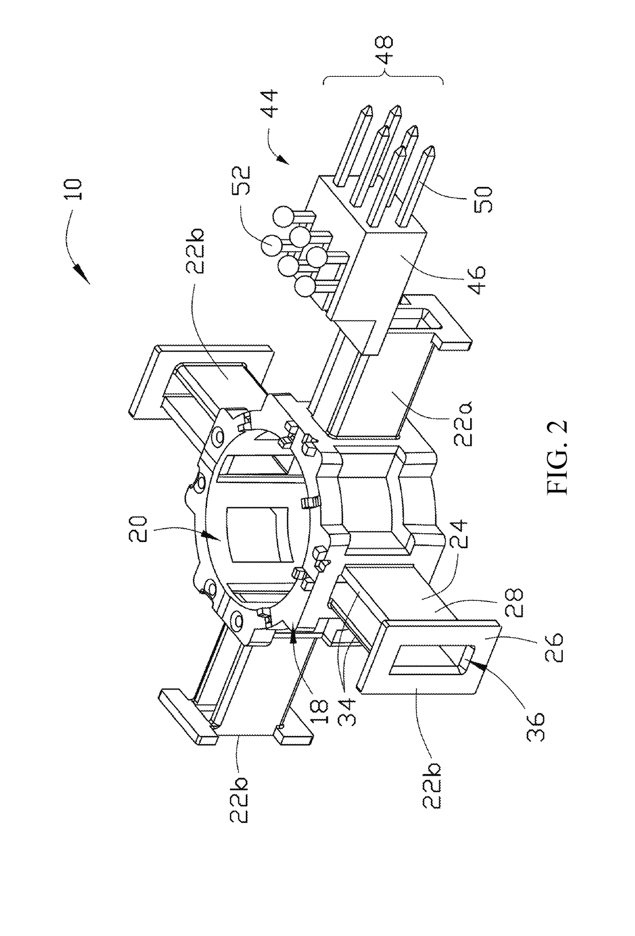
[0031]The stator 12 includes a bobbin 18, a plurality of windings 30 winding around the bobbin 18 and a core lamination unit...


PUM


Abstract

An electric motor comprising: a bobbin having a rotor receiving portion and a plurality of winding supporting portions at or adjacent to the rotor receiving portion; a rotor receivably mountable at the rotor receiving portion; a plurality of core lamination units engagable with the winding supporting portions; and a stator winding mountable about an outer surface of one of the stator engagement members. An electrical connector is also provided which has a connector body and at least one electrically-conductive element associated therewith, the connector body being integrally formed with the stator engagement member of the bobbin.

Description

CROSS REFERENCE TO RELATED APPLICATIONS[0001]This non-provisional patent application claims priority under 35 U.S.C. § 119(a) from Patent Application No. 1615848.7 filed in United Kingdom on Sep. 16, 2016.FIELD OF THE INVENTION[0002]The present invention relates to an electric motor, particularly but not necessarily exclusively to a stepper motor formed as a star motor. The invention further relates to a bobbin for such an electric motor, and also to a method of assembling the electric motorBACKGROUND OF THE INVENTION[0003]Stepper motors are electric motors which rotate in a stepwise fashion, providing very precise control over the degree of rotation of the output of the motor. There are two main ways in which such a motor is traditionally formed.[0004]A cylindrical stepper motor has a stator and a rotor which are coaxially aligned, the stator, including stator coil windings, surrounding the rotor, which can rotate relative to the stator and from which an output can be taken. Such a...

Claims


Application Information

Patent Timeline
IPC IPC(8): H02K3/32H02K7/116H02K5/04H02K11/00H02K15/14
CPCH02K3/325H02K7/116H02K5/04H02K11/0094H02K15/14H02K3/46H02K37/00H02K3/522H02K5/225H02K2203/12H02K3/52H02K3/524H02K2203/03
Inventor BOURQUI, YVAN
Owner JOHNSON ELECTRIC INTERNATIONAL AG
Why Eureka
Try Eureka