Sound suppressor for a firearm

Active Publication Date: 2015-08-04
SILENCERCO
View PDF27 Cites 33 Cited by
  • Summary
  • Abstract
  • Description
  • Claims
  • Application Information

AI Technical Summary

Benefits of technology

The sound suppressor described in this patent allows for easy assembly without needing a tube or housing. The rear end cap, baffle units, and front end cap can be snapped together, creating a tight seal and preventing gases from escaping. The configuration also allows for tailoring the length of the sound suppressor and customization of the baffle placement.

Problems solved by technology

Because the leading edge of the wad tends to expand as it is being discharged from the barrel of the shotgun and through the sound suppressor, the bushings and baffles are likely to be subjected to undesirably high incidences of so-called “baffle strike,” in which the wad and the shot that it holds contact the bushings and baffles.
Baffle strike may contaminate and damage the bushings and add to the sound that is generated as shot is discharged.
Since the sizes and locations of the ports are limited, however, they limit the volume of expanding gases that will be received by, decelerated by and cooled within the chamber(s) of the sound suppressor.
Thus, the extent to which the volume of a muzzle blast from a shotgun is decreased by such a sound suppressor may be undesirably limited.

Method used


Image

  • Sound suppressor for a firearm
  • Sound suppressor for a firearm
  • Sound suppressor for a firearm

Examples


Embodiment Construction

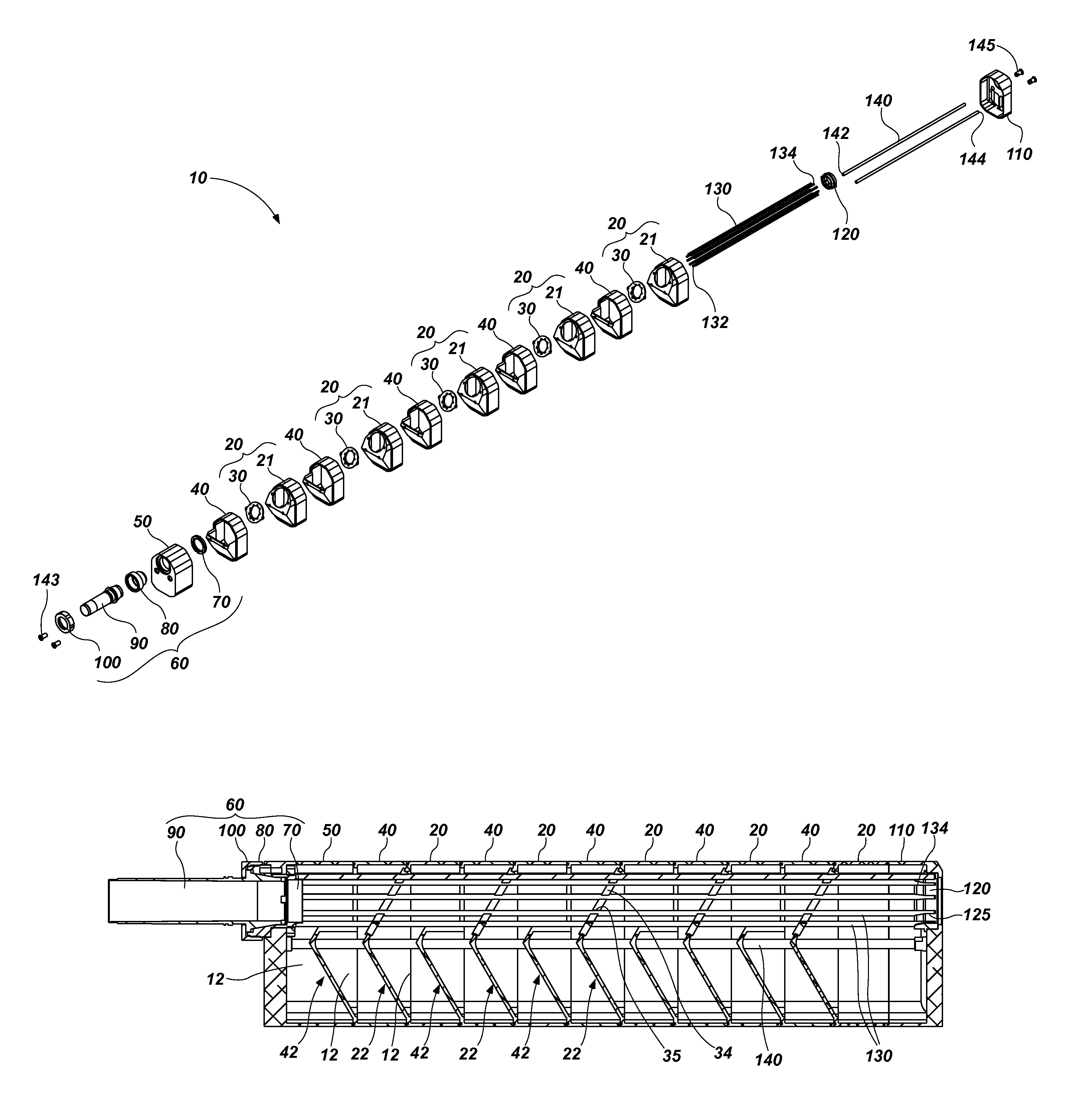
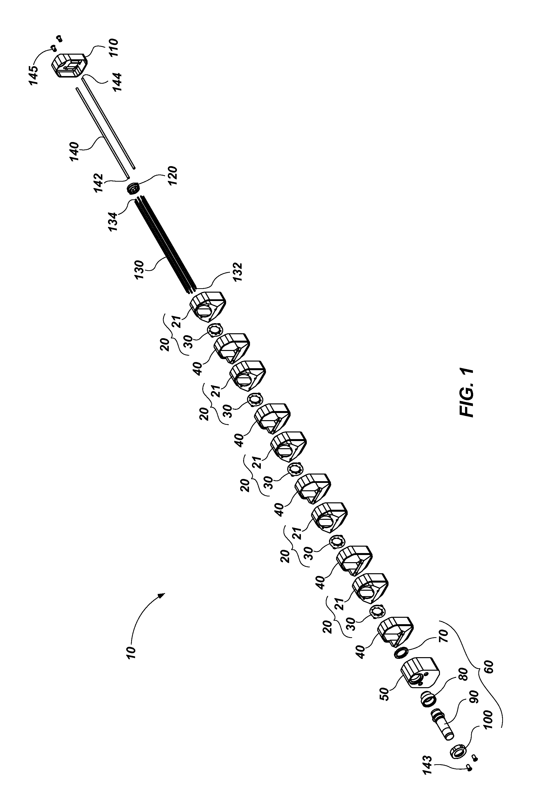
[0032]An embodiment of a sound suppressor 10 for a shotgun or another firearm is shown in FIG. 1. The sound suppressor 10 includes a plurality of baffle units 20 and 40 that are arranged and assembled in series between a rear end cap 50, which is configured to be positioned adjacent to a muzzle end of the barrel of a shotgun or another firearm, and a front end cap 110, through which shot or another projectile is to be discharged. A plurality of guide rods 130 are configured to extend through the baffle units 20 and 40, and are arranged in a manner that will guide a wad, or shot cup, and the shot contained thereby as it exits the muzzle of a firearm and travels through the interior of the sound suppressor 10.

[0033]In the embodiment shown in FIG. 1, the guide rods 130 may be arranged in a manner that forms the framework of a passage that extends through the assembled baffle units 20 and 40, but that provides sufficient open space to enable gases to flow from the passage into chambers ...


PUM


Abstract

A sound suppressor for a firearm, such as a shotgun, may include a rear end cap, a plurality of baffle units and a front end cap that are configured to be assembled in an end-to-end arrangement. These elements may be secured to one another with one or more elongated coupling elements that extend through the end-to-end arrangement, along with one or more complementary securing elements. Such a sound suppressor may lack an outer housing. A plurality of guide rods may extend through an interior of such a sound suppressor in a manner that provides the framework for a passage for a projectile as it moves through the sound suppressor. A barrel coupling element that may be used with a sound suppressor is also disclosed, as are methods for tailoring the length of a sound suppressor and for customizing the types and arrangement of baffles used in the sound suppressor.

Description

CROSS-REFERENCE TO RELATED APPLICATION[0001]A claim for the benefit of priority under 35 U.S.C. §119(e) is hereby made to U.S. Provisional Patent Application No. 62 / 026,646, filed on Jul. 20, 2014, and titled SOUND SUPPRESSOR FOR A FIREARM (“the '646 Provisional application”). This application is also a continuation-in-part of U.S. Design patent application Ser. No. 29 / 497,008, filed on Jul. 20, 2014, and titled BAFFLE UNIT FOR A SHOTGUN SOUND SUPPRESSOR (“the '008 Design application”), U.S. Design patent application Ser. No. 29 / 497,009, titled BAFFLE UNIT FOR A SHOTGUN SOUND SUPPRESSOR (“the '009 Design application”), and U.S. Design patent application Ser. No. 29 / 497,010, titled SOUND SUPPRESSOR FOR A SHOTGUN (“the '010 Design application”), all of which were filed on Jul. 20, 2014. The entire disclosures of each of the '646 Provisional application, the '008 Design application, the '009 Design application and the '010 Design application are hereby incorporated herein.TECHNICAL FIE...

Claims


Application Information

Patent Timeline
IPC IPC(8): F41A21/30F41A21/00
CPCF41A21/30
Inventor HOLDEN, HARRISONBRANDOL, CASEYSHULTS, JONATHON
Owner SILENCERCO
Why Eureka
Try Eureka