Joint for a fluid pumping apparatus

a fluid pumping and joint technology, applied in the field of joint, can solve the problems of inconvenient design, complicated structure of conventional oil pumping devices, and large volum

Inactive Publication Date: 2006-09-12
TSENG TIEN TSAI
View PDF15 Cites 3 Cited by
  • Summary
  • Abstract
  • Description
  • Claims
  • Application Information

AI Technical Summary

Benefits of technology

[0006]The main objective of the present invention is to provide an improved joint for a fluid pumping apparatus.

Problems solved by technology

A conventional oil-pumping device usually has a complicated structure and a great volume.
It is an inconvenient design.
Consequently, the user often needs to clean the container after the being used for next use when sucking the fluid that is different from the previous operation.

Method used


Image

  • Joint for a fluid pumping apparatus
  • Joint for a fluid pumping apparatus
  • Joint for a fluid pumping apparatus

Examples


Embodiment Construction

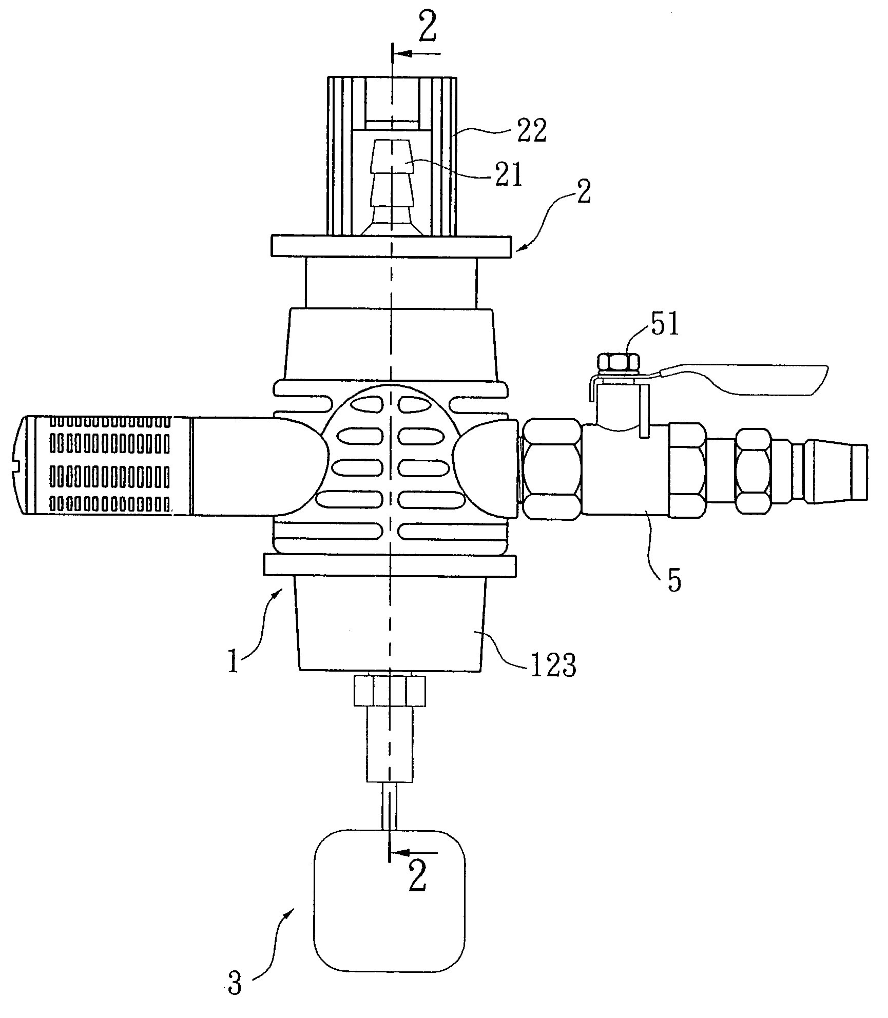
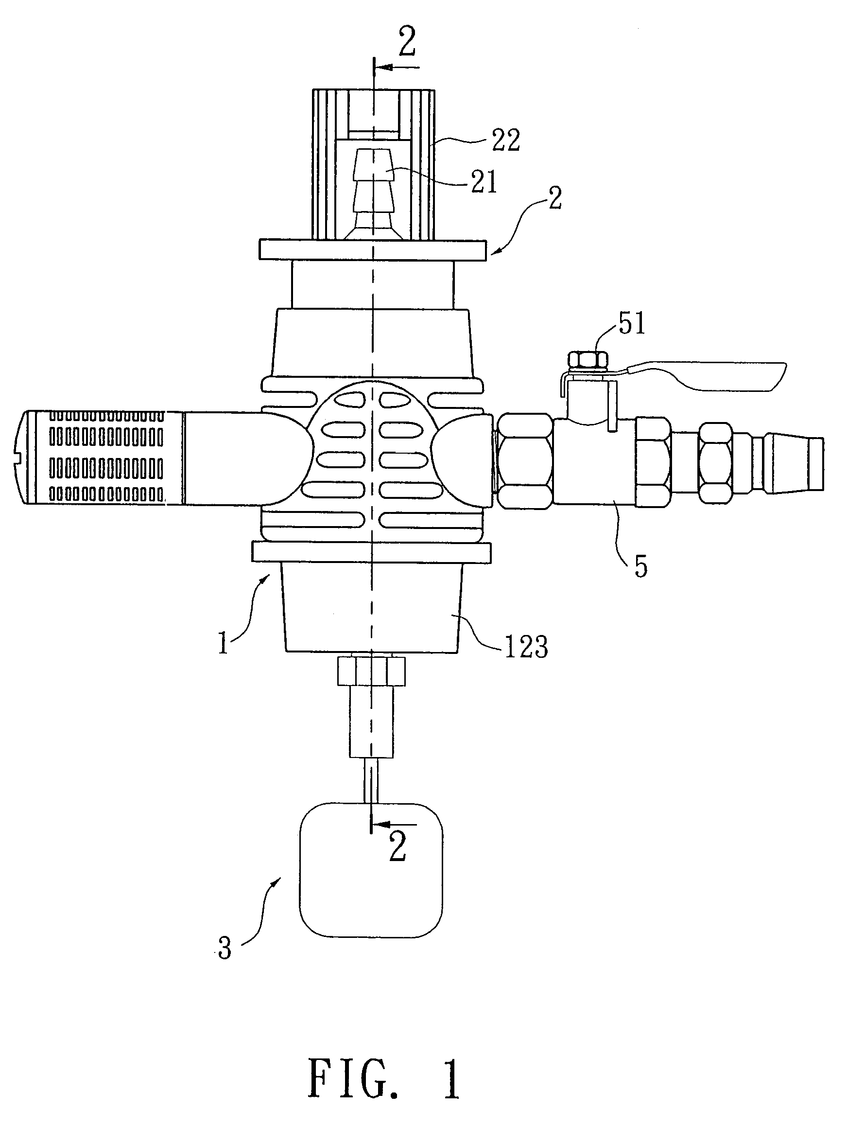
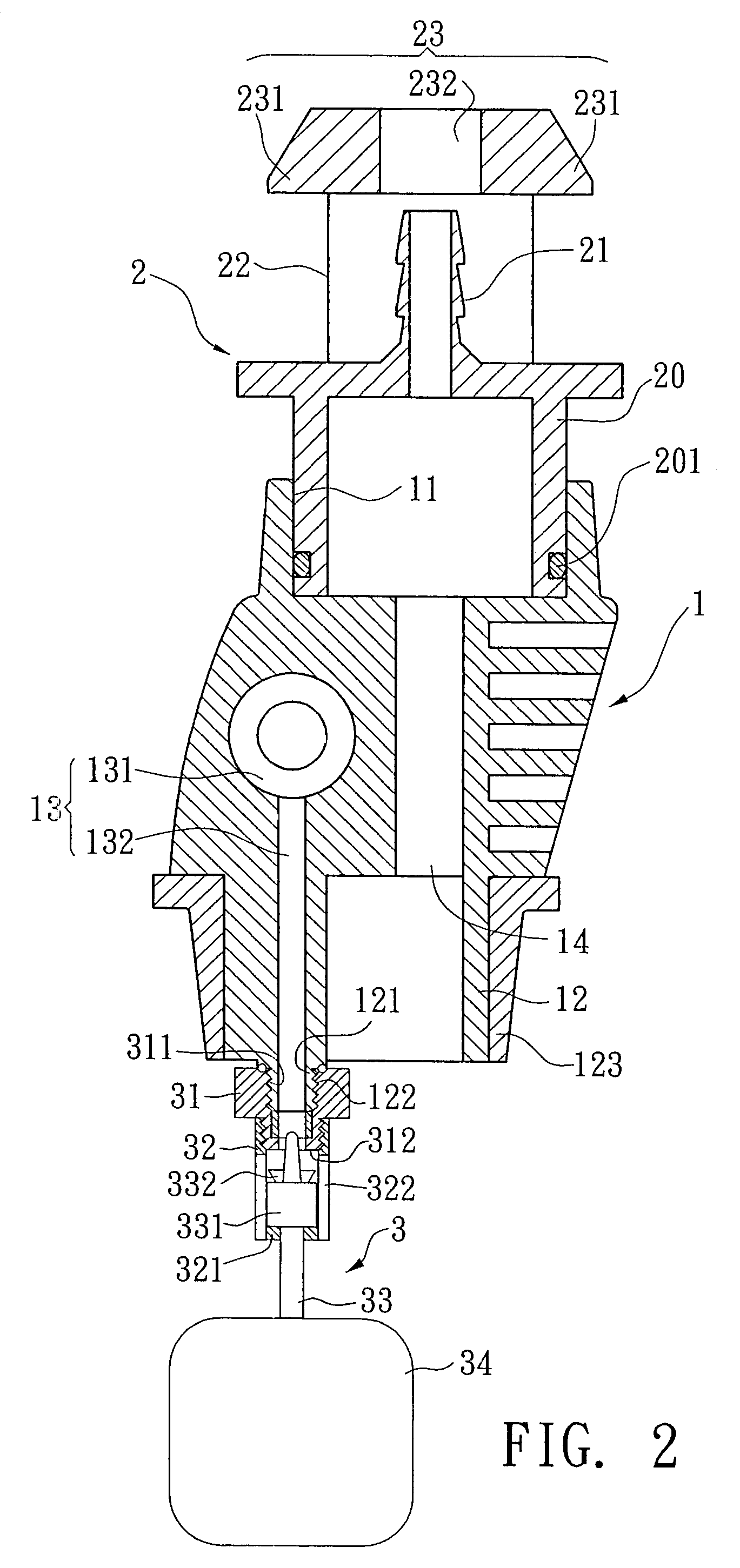
[0014]Referring to the drawings and initially to FIGS. 1 and 2, a joint for a fluid pumping apparatus in accordance with the present invention comprises a body (1), a connecting seat (2) movably mounted to an upper portion of the body (1) and an automatic stop device (3) movably mounted to a lower portion of the body (1).

[0015]The body (1) comprises a trough (11) defined in the upper portion of the body (1) for partially receiving the connecting seat (2). In the preferred embodiment of the present invention, the trough (11) is circular. An insertion (12) downward extends from the lower portion of the body (1) and a tapered sealant (123) is mounted around the insertion (12). The sealant (123) is made of rubber, silica gel and the like. The diameter of the sealant (123) is gradually reduced relative to a distal end of the insertion (12) for providing an airtight effect when the insertion (12) is inserted into an opening (not numbered) of a container (4), as shown in FIGS. 3 and 4. A T...


PUM

PropertyMeasurementUnit
pressureaaaaaaaaaa
diameteraaaaaaaaaa
atmospheric pressureaaaaaaaaaa

Abstract

A joint for a fluid pumping apparatus includes a body having a passage defined in the body and extending through the body. A through hole is longitudinally defined in the body and extends through the body. A container is mounted to a lower end of the body, and the passage and the through hole communicate with the interior of the container. A connecting seat in mounted to an upper end of the body and has hollow connector communicating with the through hole in the body. A hose has a first end connected to the hollow connector and a second extending into a pail containing fluid. Consequently, the fluid in the pail can be sucked into the container when a compressed air flows through the passage in the body.

Description

BACKGROUND OF THE INVENTION[0001]1. Field of the Invention[0002]The present invention relates to a joint, and more particularly to a joint for a fluid pumping apparatus.[0003]2. Description of Related Art[0004]A conventional oil-pumping device usually has a complicated structure and a great volume. It is an inconvenient design. Further, the container of the conventional oil-pumping device for receiving the pumped oil uniquely corresponds to the oil-pumping device. Consequently, the user often needs to clean the container after the being used for next use when sucking the fluid that is different from the previous operation.[0005]The present invention has arisen to mitigate and / or obviate the disadvantages of the conventional oil-pumping device.SUMMARY OF THE INVENTION[0006]The main objective of the present invention is to provide an improved joint for a fluid pumping apparatus.[0007]To achieve the objective, the joint in accordance with the present invention comprises a body includin...

Claims


Application Information

Patent Timeline
Patent Type & Authority Patents(United States)
IPC IPC(8): B65B31/04F04F3/00F16L21/00
CPCF04F3/00Y10T137/3109
Inventor TSENG, TIEN TSAI
Owner TSENG TIEN TSAI
Why Eureka
Try Eureka