Method for producing a hollow profile joint and a hollow profile

a technology of profile joint and hollow profile, which is applied in the direction of gas flame welding apparatus, furniture joining, welding apparatus, etc., can solve the problems of limited strength of such joints, limited stability, and limited strength of material joints, so as to improve welding results, improve strength, and control the joining process.

Inactive Publication Date: 2011-11-10
BENTELER AUTOMOBILTECHNIK GMBH
View PDF1 Cites 2 Cited by
  • Summary
  • Abstract
  • Description
  • Claims
  • Application Information

AI Technical Summary

Benefits of technology

[0024]Advantageously, thermal joining is performed in an inert gas, which allows a particularly good control of the joining process. The inert gas is typically argon, wherein depending on the component, addition of helium, up to a mass fraction of 50%, can improve the welding outcome.
[0025]In another advantageous embodiment, thermal joining may be performed with a single layer or with several layers. Implementation of a multilayer joining process can intentionally target the required properties of the joint. Advantages are increased strength and a reduced thermal effect in the welding zone. In a multilayer welding process, a large quantity of welding deposit need not be materially connected in a single operation. The additive can be applied in several layers.
[0026]Advantageously, during the thermal joining, the weld seam may be mechanically and / or chemically cleaned between the depositions of individual layers. Such cleaning may be performed, for example, with dry ice blasting. The cleaned weld seam produces an improved joint and an improved welding result for the weld seam to be applied later, as compared to an untreated weld seam.

Problems solved by technology

However, the strength of such joint is limited due to the point-wise force transfer.
The aforedescribed cold joining methods, for example riveting or adhesive techniques, do not lead to the required stability.
However, these material joints also have only limited strength.
Also disadvantageous is the existence of a gap between the cast aluminum part and the steel pipe.
Ambient air may enter the melt through this gap during the welding process, resulting in a weld of poor quality and hence low strength.
Moreover, moisture can reach the steel-aluminum transition during the operation, causing additional gap corrosion.

Method used


Image

  • Method for producing a hollow profile joint and a hollow profile
  • Method for producing a hollow profile joint and a hollow profile
  • Method for producing a hollow profile joint and a hollow profile

Examples


Embodiment Construction

[0033]Throughout all the figures, same or corresponding elements may generally be indicated by same reference numerals. These depicted embodiments are to be understood as illustrative of the invention and not as limiting in any way. It should also be understood that the figures are not necessarily to scale and that the embodiments are sometimes illustrated by graphic symbols, phantom lines, diagrammatic representations and fragmentary views. In certain instances, details which are not necessary for an understanding of the present invention or which render other details difficult to perceive may have been omitted.

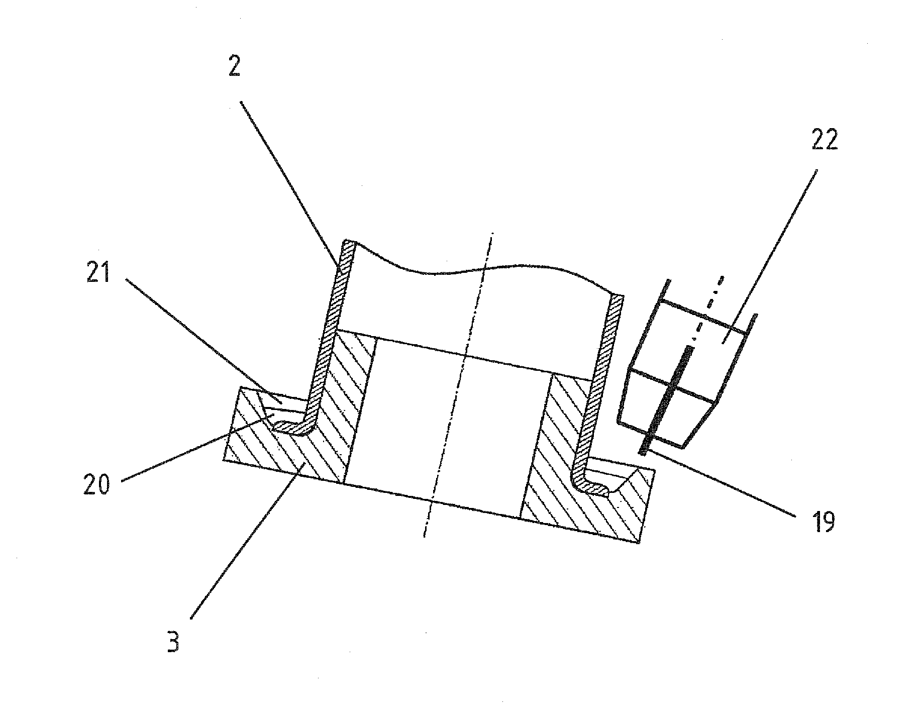
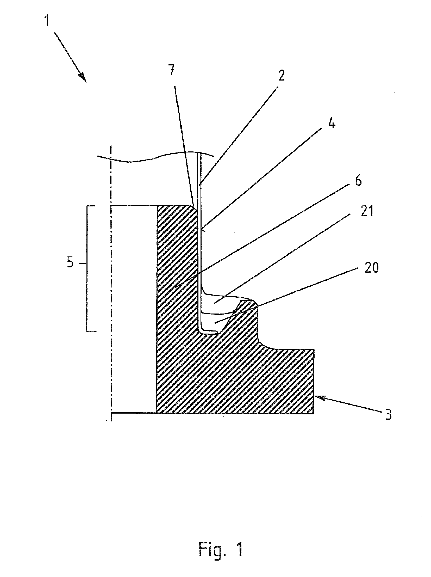
[0034]Turning now to the drawing, and in particular to FIG. 1, there is shown a joint 1 according to the invention between a hollow profile 2 and a component 3. The hollow profile 2 is constructed from steel, whereas the component 3 is constructed from aluminum, preferably as a cast aluminum body. A coating 4 is applied to the hollow profile 2 at least in a seating region 5....


PUM

PropertyMeasurementUnit
angleaaaaaaaaaa
angleaaaaaaaaaa
lengthaaaaaaaaaa

Abstract

In a method for producing a joint between a hollow profile made from steel and a component made from an aluminum material, a positive and material joint is produced by a braze welding process in conjunction with a pressing operation. The hollow profile is first pressed on a seating region of the component. Subsequently, a weld layer with an additive is applied by thermal joining, producing a positive and material joint between the hollow profile and the component. The positive joint is facilitated by first forming an end of the hollow profile to be pressed on. Preferably, forming is done by widening the end to be pressed on into the shape of a collar.

Description

CROSS-REFERENCES TO RELATED APPLICATIONS[0001]This application claims the priority of German Patent Application, Serial No. 10 2009 051 951.3-24, filed Nov. 4, 2009, pursuant to 35 U.S.C. 119(a)-(d), the content of which is incorporated herein by reference in its entirety as if fully set forth herein.BACKGROUND OF THE INVENTION[0002]The present invention relates to a method for producing a joint between a hollow profile made from steel and a component made from an aluminum material. The present invention also relates to a hollow profile joint of a hollow profile made from steel with a component made from an aluminum material.[0003]The following discussion of related art is provided to assist the reader in understanding the advantages of the invention, and is not to be construed as an admission that this related art is prior art to this invention.[0004]In the context of the present specification and claims, the term “positive fit” or “positively” is meant to indicate a form-fitting o...

Claims


Application Information

Patent Timeline
Patent Type & Authority Applications(United States)
IPC IPC(8): F16B11/00B23K31/02B23K20/24
CPCB23K9/028B23K9/232Y10T403/477Y10T29/4998B23K2203/20B23K2103/20
Inventor POTTHAST, SIMONFECKE, SIEGFRIEDWIBBEKE, MICHAELKROGMEIER, JURGENZUBER, ARMIN
Owner BENTELER AUTOMOBILTECHNIK GMBH
Why Eureka
Try Eureka