User terminal, radio base station and radio communication method
a radio communication method and user terminal technology, applied in the direction of wireless communication, transmission path division, spectral gap assessment, etc., can solve the problem of significant cross-interference produced in comparison to a licensed band, and achieve the effect of adequate ul transmission
- Summary
- Abstract
- Description
- Claims
- Application Information
AI Technical Summary
Benefits of technology
Problems solved by technology
Method used
Image
Examples
first example
Example of Operation with First Example
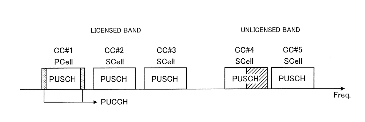
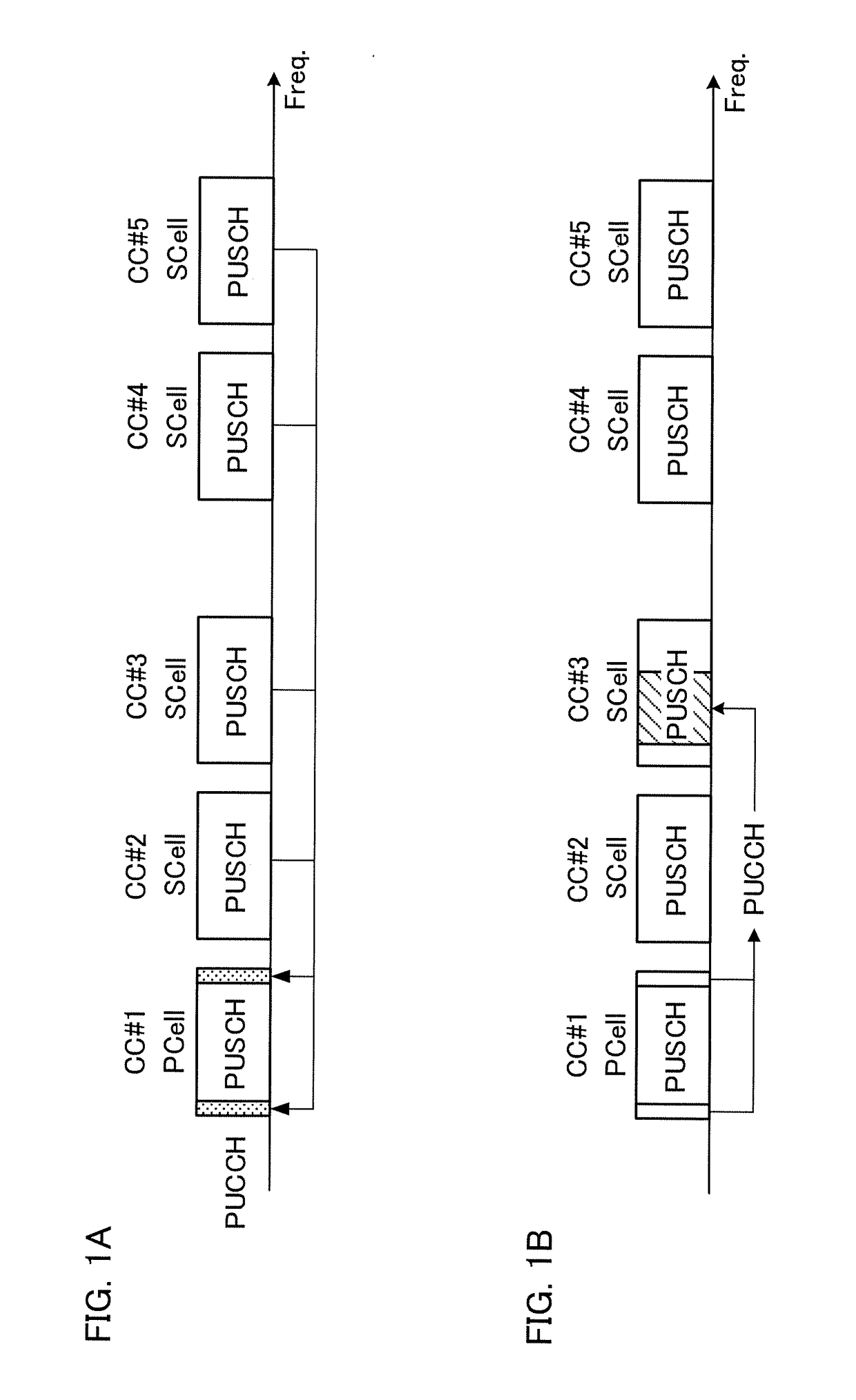
[0073]A user terminal that can use simultaneous PUCCH-PUSCH transmission (across CCs) transmits uplink control information, by employing UCI on PUSCH or simultaneous PUCCH-PUSCH transmission, following predetermined rules. The predetermined rules which the user terminal follows vary between when PUSCH transmission takes place in licensed band CCs and when PUSCH transmission does not take place in licensed band CCs but takes place in unlicensed band CCs.
[0074]When a PUSCH is not transmitted in a licensed band CC and a PUSCH is transmitted in an unlicensed band CC, the user terminal employs simultaneous PUCCH-PUSCH transmission (see FIG. 6A). Also, when one of a HARQ-ACK / SR and P-CSI is included in uplink control information, the user terminal transmits the uplink control information in a PUCCH. When both a HARQ-ACK / SR and P-CSI are included in uplink control information, the user terminal transmits part of the uplink control information (HARQ-AC...
second example
Example of Operation with Second Example
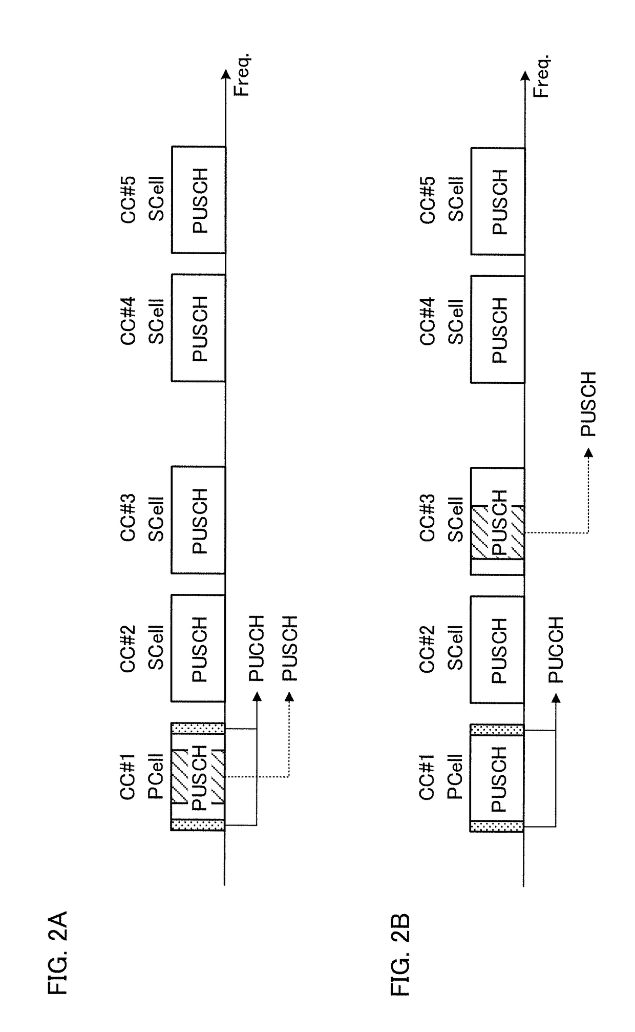
[0076]A user terminal that cannot use simultaneous PUCCH-PUSCH transmission (across CCs) transmits uplink control information, by employing UCI on PUSCH or simultaneous PUCCH-PUSCH transmission, following predetermined rules. The predetermined rules which the user terminal follows vary between when PUSCH transmission takes place in licensed band CCs and when PUSCH transmission does not take place in licensed band CCs but takes place in unlicensed band CCs.
[0077]When a PUSCH is not transmitted in a licensed band CC and a PUSCH is transmitted in an unlicensed band CC, the user terminal drops the unlicensed band CC's PUSCH, and transmits uplink control information in the PUCCH of the PCell (see FIG. 7A).
[0078]When PUSCH transmission takes place in a licensed band CC, the user terminal multiplexes (piggyback) and transmits uplink control information on the PUSCH of one licensed band CC (see FIG. 7B). In this case, if a PUSCH is transmitted in the ...
third example
[0079]Referring back to the first example, which method of simultaneous PUCCH-PUSCH transmission (FIG. 6A) and UCI on PUSCH (FIG. 6B) a user terminal uses can be judged based on whether the CC to perform UL transmission is a licensed band CC or an unlicensed band CC. Similarly, referring back to the second example, which method of dropping a PUSCH and transmitting a PUCCH (FIG. 7A), and UCI on PUSCH (FIG. 7B) a user terminal uses can be judged based on whether the CC to perform UL transmission is a licensed band CC or an unlicensed band CC. However, the present embodiment is by no means limited to the method of making judgments based whether a licensed band is used or an unlicensed band CC is used.
[0080]For example, in the first example, information to identify a CC, to which a user terminal should apply simultaneous PUCCH-PUSCH transmission (FIG. 6A) or UCI on PUSCH (FIG. 6B), may be reported in advance to the user terminal through higher layer signaling. The information to include...
PUM
 Abstract
Description
Claims
Application Information
 - R&D
- Intellectual Property
- Life Sciences
- Materials
- Tech Scout
- Unparalleled Data Quality
- Higher Quality Content
- 60% Fewer Hallucinations
Browse by: Latest US Patents, China's latest patents, Technical Efficacy Thesaurus, Application Domain, Technology Topic, Popular Technical Reports.
© 2025 PatSnap. All rights reserved.Legal|Privacy policy|Modern Slavery Act Transparency Statement|Sitemap|About US| Contact US: help@patsnap.com


