Fiber optic communication system with automatic line shutdown/power reduction

Active Publication Date: 2009-06-04
IPG PHOTONICS CORP
View PDF20 Cites 11 Cited by
  • Summary
  • Abstract
  • Description
  • Claims
  • Application Information

AI Technical Summary

Benefits of technology

[0018]A further aspect of the disclosure includes the direct modulation of the pump diodes of an Er fiber laser as a transmitter of the OB OSC's control signal. If not for the direct modulation, the OB OSC would be configured with a standard semiconductor laser having its output op

Problems solved by technology

However, such an explosion has brought many challenges to the telecommunication industry to develop technology that will greatly expand the bandwidth limitations of existing communication systems.
As the complexity and power of optical communication systems increase, the demand for additional diagnostics and safety measure associated with the modern systems is being raised as well.
The moment there is a fiber break, which can happen due to a number of e

Method used


Image

  • Fiber optic communication system with automatic line shutdown/power reduction
  • Fiber optic communication system with automatic line shutdown/power reduction
  • Fiber optic communication system with automatic line shutdown/power reduction

Examples


Example

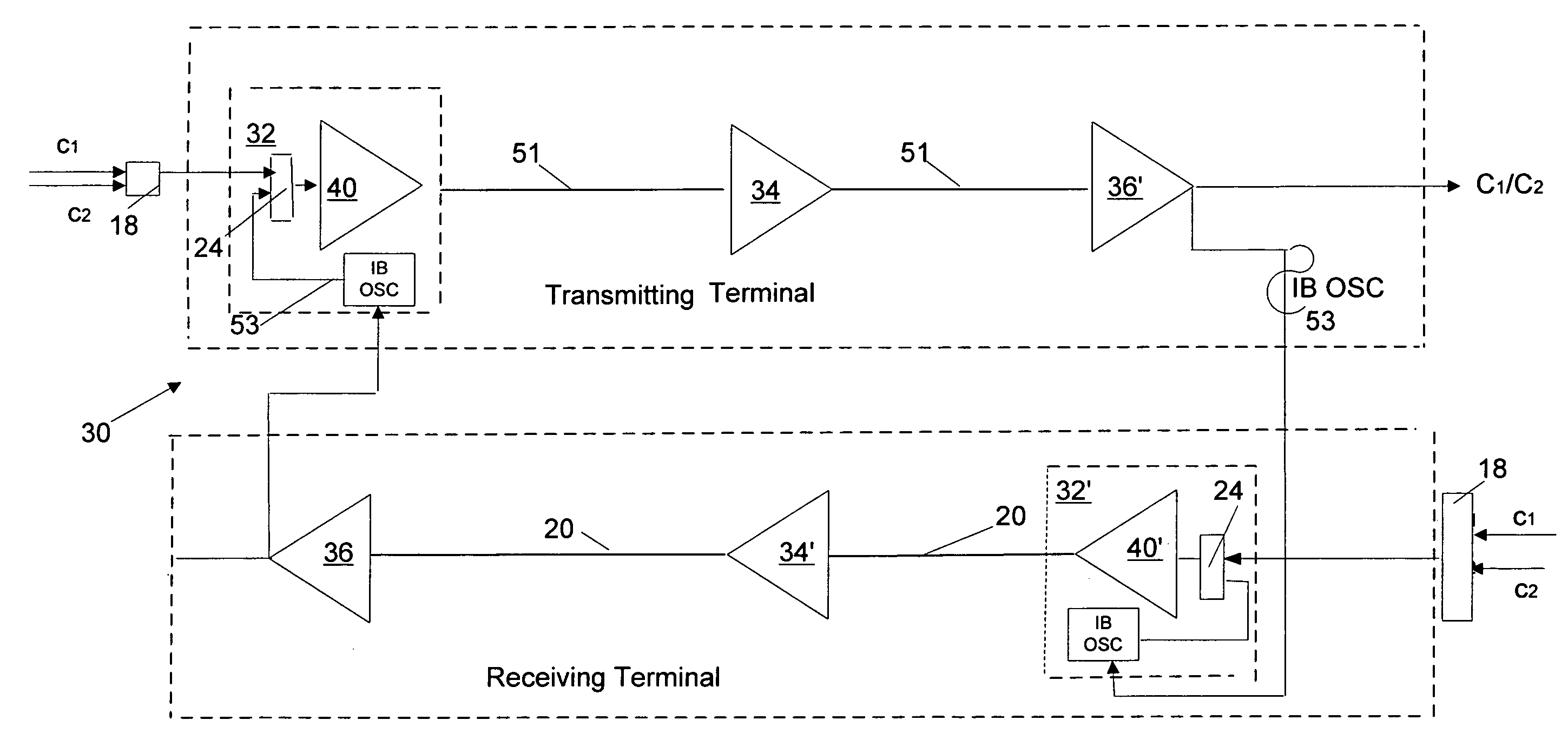
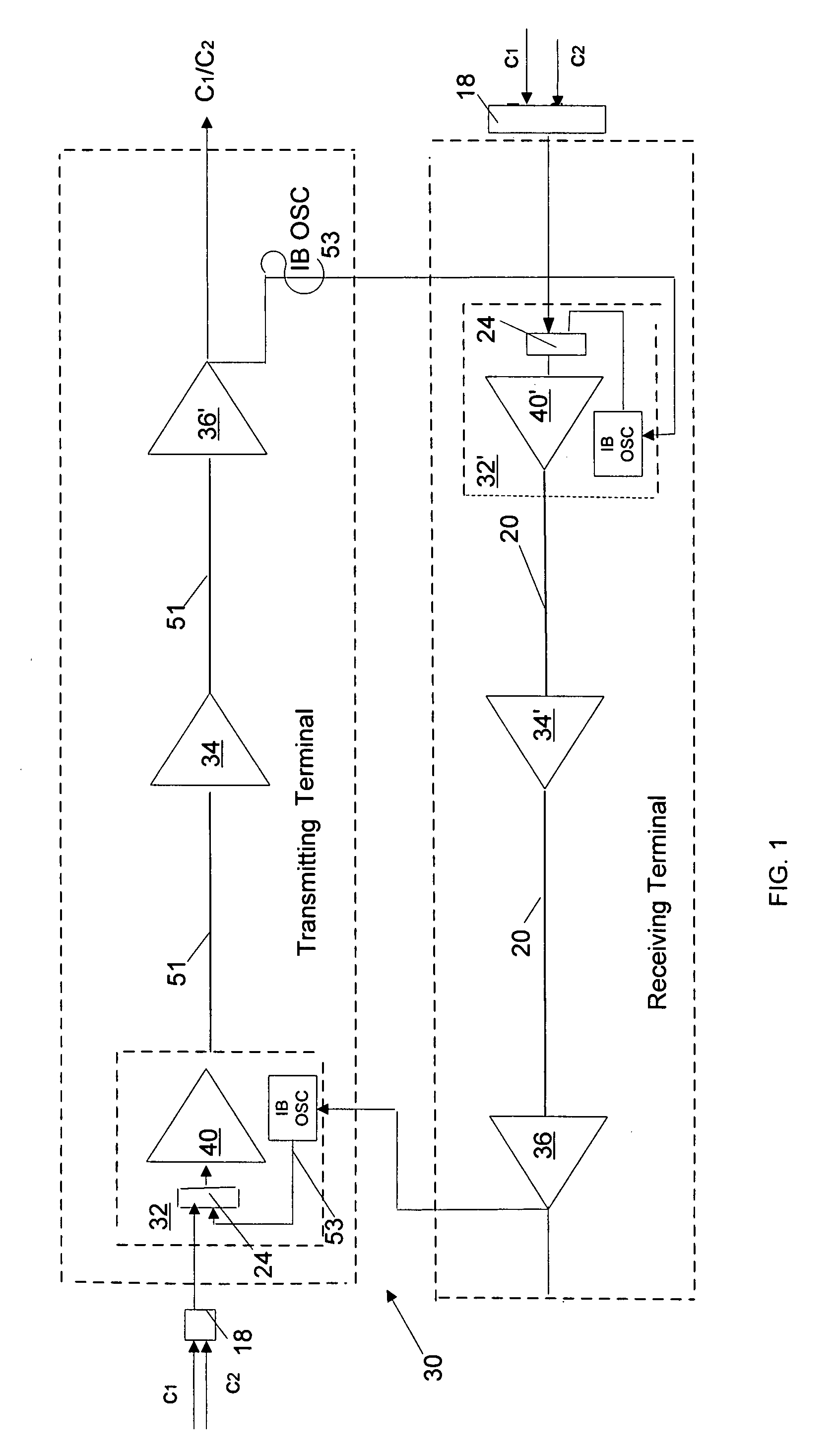
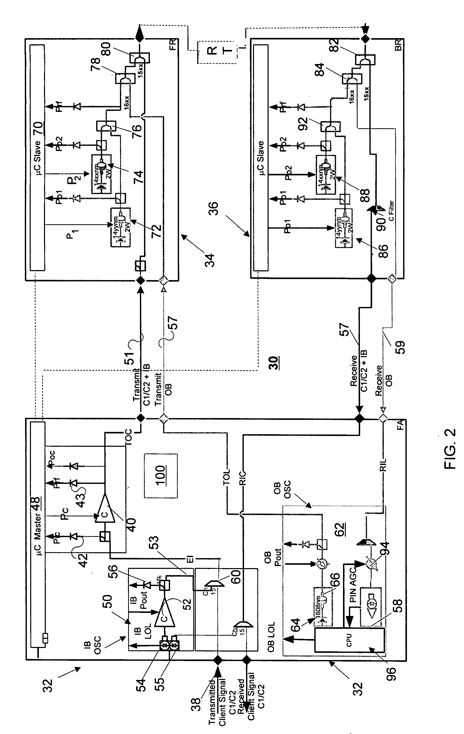
[0028]Reference will now be made in detail to several embodiments of the invention that are illustrated in the accompanying drawings. Wherever possible, same or similar reference numerals are used in the drawings and the description to refer to the same or like parts or steps. The drawings are in simplified form and are not to precise scale. The words “connect,”“couple,” and similar terms do not necessarily denote direct and immediate connections, but also include connections through intermediate elements or devices. In some instances, well-known structures and devices are disclosed in block-diagram form in order to avoid unnecessarily obscuring the disclosure. Although the disclosure is discussed with respect to ultra-long-haul WDM and DWDM systems, all inventive aspects have application to other types of optical communication systems.

[0029]FIG. 1 diagrammatically illustrates the inventive WDM fiber-optic communication system 30 providing transmission of WDM client optical signals ...


PUM


Abstract

A wavelength division multiplexing (WDM) fiber optic communication system is operative to transmit WDM signals between multiple nodes. Each of the nodes has a booster EDFA, and in-band (IB) and out-of-band (OB) supervisory channels operative to monitor the integrity of a transmission link by generating and detecting respective in-band and out-of-band control signals. The booster EDFA is operative to receive the multiplexed WDM and IB signals and generate an output signal carried by a plurality of fiber-optic cables between the nodes. The booster EDFA is operative to switch from an automatic gain control regime upon detecting of at least one of the IB and OB signals to an automatic power control regime upon loss of both IB and OB signals. The output signal of the EDFA in the AGC regime has a high power sufficient for being transmitted the WDM and IB signals, and has a low power in the APC regime sufficient for transmitting only the IB signal between the nodes.

Description

BACKGROUND OF THE INVENTION[0001]1. Field of the Invention[0002]The invention relates to a system for transmitting optical signals in optical fibers at long distances between locations. In particular, the invention relates to a system operative to monitor and control the integrity of transmission fibers and functionality of the system's components.[0003]2. Prior Art Discussion[0004]The unprecedented growth of communication services has spawned a new era of personal and business interactions. However, such an explosion has brought many challenges to the telecommunication industry to develop technology that will greatly expand the bandwidth limitations of existing communication systems. Optical communications holds great promise to meet the continual demands for greater and greater bandwidth.[0005]In particular, Wavelength Division Multiplexing (WDM) technology, and even more specifically Dense WDM (DWDM), allows for the concurrent transmission of multiple channels over a common optic...

Claims


Application Information

Patent Timeline
IPC IPC(8): H04J14/02
CPCH04B10/0771H04J14/0221H04B10/0775
Inventor BUABBUD, GEORGEMORNATTA, CRISTIANOREEVES-HALL, PETERSAMARTSEV, IGOR
Owner IPG PHOTONICS CORP
Why Eureka
Try Eureka