
Cooling Control Systems

a control system and cooling system technology, applied in the direction of process and machine control, machines/engines, instruments, etc., can solve the problems of insufficient monitoring of the amount of coolant in the cooling system, damage to the cooling system, and failure of the cooling system, so as to reduce the operation of the cooling system.

Active Publication Date: 2018-03-29
GE GLOBAL SOURCING LLC
View PDF7 Cites 9 Cited by
  • Summary
  • Abstract
  • Description
  • Claims
  • Application Information

AI Technical Summary

Benefits of technology

The patent describes a cooling control system for vehicles that can detect when the cooling system is running at low levels and prevent the vehicle from moving without stopping. The system uses sensors to measure the amount of coolant in the system and calculates the distance or time the vehicle can continue moving before the coolant levels become too low. The system can also adjust the flow rate of the coolant based on external conditions to ensure optimal cooling efficiency. Overall, the system improves cooling performance and prevents damage to the vehicle's components in case of a cooling emergency.

Problems solved by technology

Over time, cooling systems may become damaged and / or fail.
Some vehicles may respond to failure in a cooling system by stopping movement of the vehicle.
But, this can cause significant problems in some circumstances.
But, for some mobile powered systems, such as vehicles, simply monitoring the amount of coolant in the cooling system may be insufficient.
The coolant level may become too low at a time that the vehicle is far from a source or supply of additional coolant.
Monitoring of the amount of coolant and / or the temperature of the coolant in a cooling system can be complicated by factors other than the amount of coolant.
When the amount of coolant becomes too low, for example, a pump of the cooling system may ingest air instead of the coolant.
This can cause cavitation in the cooling system.
Cavitation in the cooling system can cause the pressure of the coolant in the cooling system to significantly decrease, leading to a reduced ability to cool the powered system.
As another example, the measured temperature of coolant in a cooling system may be erroneously hot when a heat exchanger, cooling fan, or other component of the cooling system fails.
But, in conditions where the air density is greater than the assumed low air density, then the blowers may be operating at an unnecessarily fast speed.

Method used


Image

  • Cooling Control Systems
  • Cooling Control Systems
  • Cooling Control Systems

Examples


Embodiment Construction

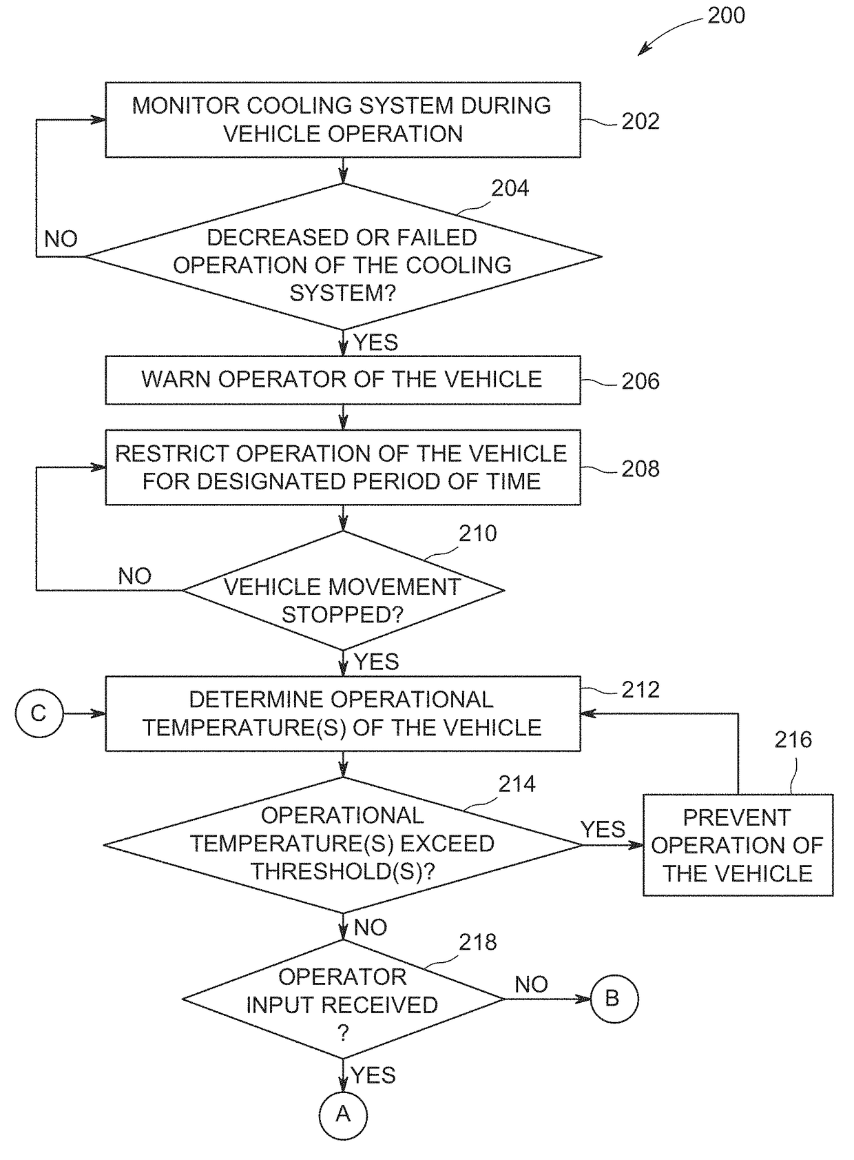
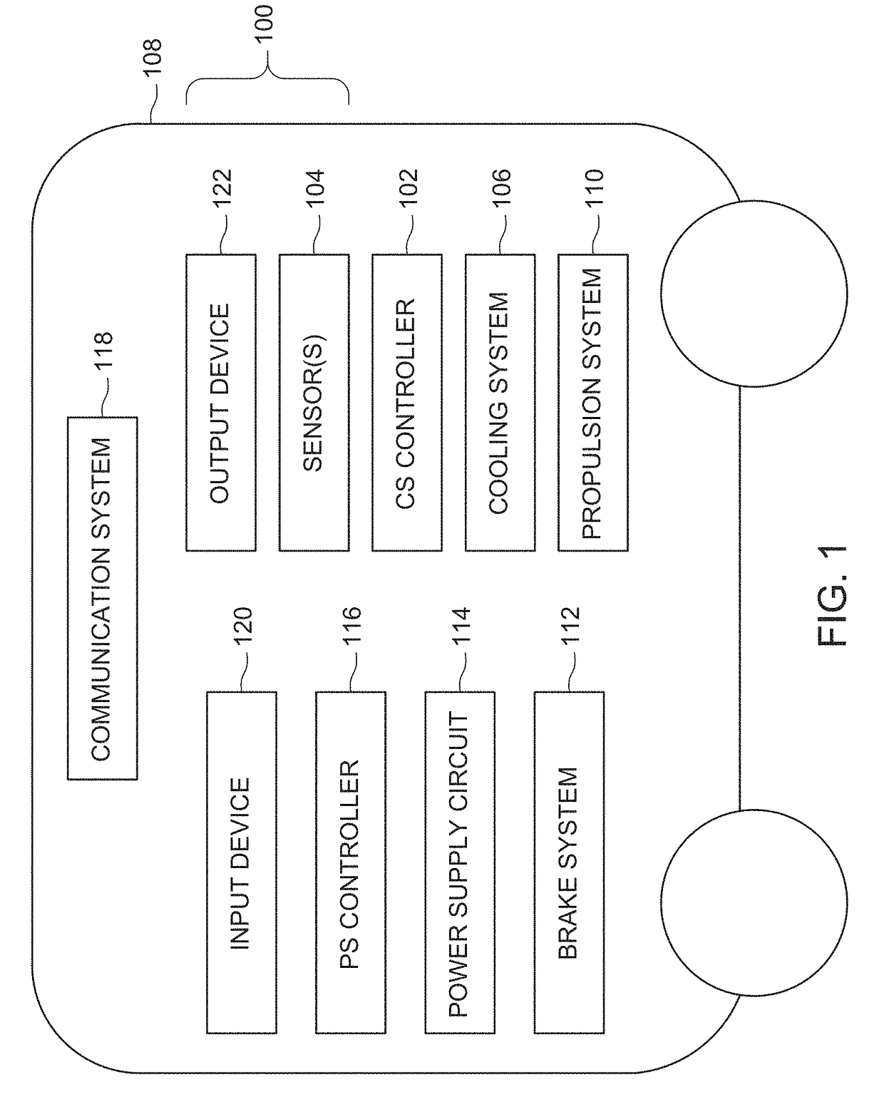
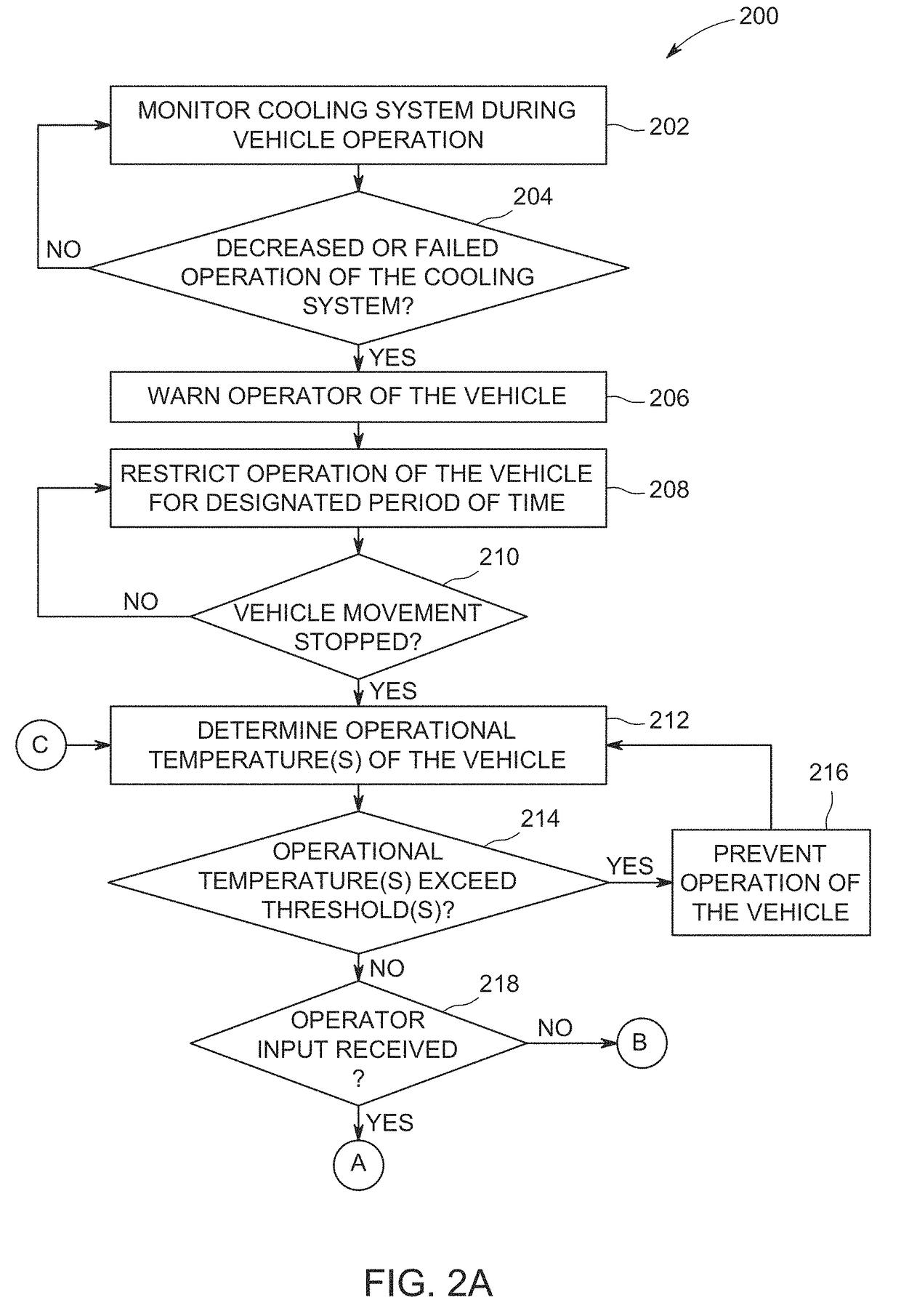
[0021]One or more embodiments of the inventive subject matter described herein provide control systems and methods that monitor operation of cooling systems of powered systems (e.g., vehicles) and that restrict how the powered systems are controlled responsive to detecting a problem (e.g., failure or an insufficient ability to cool) with a cooling system. At least one technical effect of the inventive subject matter described herein is the safe control of a vehicle responsive to identifying a cooling system failure that results in the powered system being moved to a location that does not restrict or block movement of other vehicles while avoiding damage to other components (e.g., the components previously being cooled by the failed cooling system).

[0022]Other embodiments of the inventive subject matter described herein provide control systems and methods that monitor coolant levels in cooling systems and predict how much longer a powered system can operate and / or how much farther a...


PUM


Abstract

Cooling control systems described herein detect decreased operation of a cooling system of a vehicle, restrict movement of the vehicle without stopping movement responsive to decreased operation of the cooling system, and restrict movement of the vehicle by preventing the vehicle from traveling at a speed and / or power output for a non-zero designated period of time. This can allow for the vehicle to continue moving for a temporary period of time to avoid blocking traffic. Other control systems determine predicted distances and / or times that the vehicle can continue moving before coolant in the cooling system decreases below a designated threshold. Movement of the vehicle can be changed responsive to an upcoming distance and / or time that the vehicle is to travel exceeding the predicted distance and / or time. Other control systems modify a coolant flow rate based on differences between designated and ambient conditions.

Description

FIELD[0001]Embodiments of the subject matter disclosed herein relate to systems that control and / or monitor operations of cooling systems.BACKGROUND[0002]Various powered systems may include cooling systems to maintain temperatures of components of the powered systems at safe levels. For example, vehicles may include cooling systems that pump fluid coolant (e.g., liquid coolant or air) through and / or around engines, inverters, transformers, motors, alternators, etc., in order to keep the temperatures of the engines, inverters, transformers, motors, alternators, etc., sufficiently low to prevent damage to these components.[0003]Over time, cooling systems may become damaged and / or fail. Some vehicles may respond to failure in a cooling system by stopping movement of the vehicle. But, this can cause significant problems in some circumstances. For example, the vehicle with a failed cooling system may abruptly stop in a location that blocks movement of other vehicles, such as may occur in...

Claims


Application Information

Patent Timeline
Patent Type & Authority Applications(United States)
IPC IPC(8): B60R16/023B60K11/06F01P11/18B60K11/08B60K31/00
CPCB60R16/0232B60K11/06F01P11/18F01P2031/34B60K31/00F01P2050/22B60K11/085B60K11/02F01P11/16Y02T10/88B60W50/038B60W2720/10
Inventor PETRAK, EDWARD THOMASSTRODE, JASONYOUNG, HENRY TODDBROWN, TIMOTHY WARRENKUTTENKULER, JASON DANIELZILL, JR., ROBERT JOHNNEDLEY, KENNETH PAULWOLFF, JEFFREY JOHNGANGWAL, PRITAMKUMARGADIYARAM, JANAKIABDOLLAHI, MARYAMISHAKU, JOSEPH AUDUTOLLEFSON, CHRISTIAN ROLANDDODIS, LINDSEYKATUKAM, SHIVAKUMAR
Owner GE GLOBAL SOURCING LLC
Features
  • Generate Ideas
  • Intellectual Property
  • Life Sciences
  • Materials
  • Tech Scout
  • Unparalleled Data Quality
  • Higher Quality Content
  • 60% Fewer Hallucinations
Learn More