Automated wash method for a progressing cavity pump system

a technology of automatic washing and cavity pump, which is applied in the direction of survey, instruments, borehole/well accessories, etc., can solve the problems of increasing the torque requirement of the pump, reducing the fluid velocity, and affecting the rotation of the eccentric rotor pin and the drive string of the sucker rod, so as to increase the speed of the pc pump

Active Publication Date: 2018-03-29
BRISTOL
View PDF0 Cites 5 Cited by
  • Summary
  • Abstract
  • Description
  • Claims
  • Application Information

AI Technical Summary

Benefits of technology

[0010]In accordance with a first exemplary aspect of the disclosure, an automated wash system for use with a progressing cavity (PC) pump system is disclosed. The PC pump system has a well casing with an annulus, a progressing cavity (PC) pump disposed within the well casing, a motor operatively coupled to the PC pump, a controller operatively coupled to the motor, and a gas flow valve in communication with the annulus and operatively coupled to the controller. The automated wash system comprises a wash fluid source adapted to be operably coupled to th...

Problems solved by technology

This restriction results in increased torque requirement for the pump and can further decrease fluid velocity.
If the solid material accumulates at the top of the pump, it can interfere with the rotation of an eccentric rotor pin and sucker rod drive string.
The problem can gradually compound, resulting in a situation where the pump can no longer pump fluid to the surface.
Such interventions, however, are costly and result in considerable unproductive time for the well.
In some cases, the action taken to clear the well conduit can result in sand or silt being pushed into the producing formation, which is an undesirable situation that might detract from the ultimate recovery of the well.
Although solids accumulation in the production conduit is an undesirable situation for any oil or gas well, it is especially problematic in coalbed methane wells.
In coalbed methane production, the downtime associated with a “sand up” condition is particularly detrimental to production...

Method used


Image

  • Automated wash method for a progressing cavity pump system
  • Automated wash method for a progressing cavity pump system
  • Automated wash method for a progressing cavity pump system

Examples


Embodiment Construction

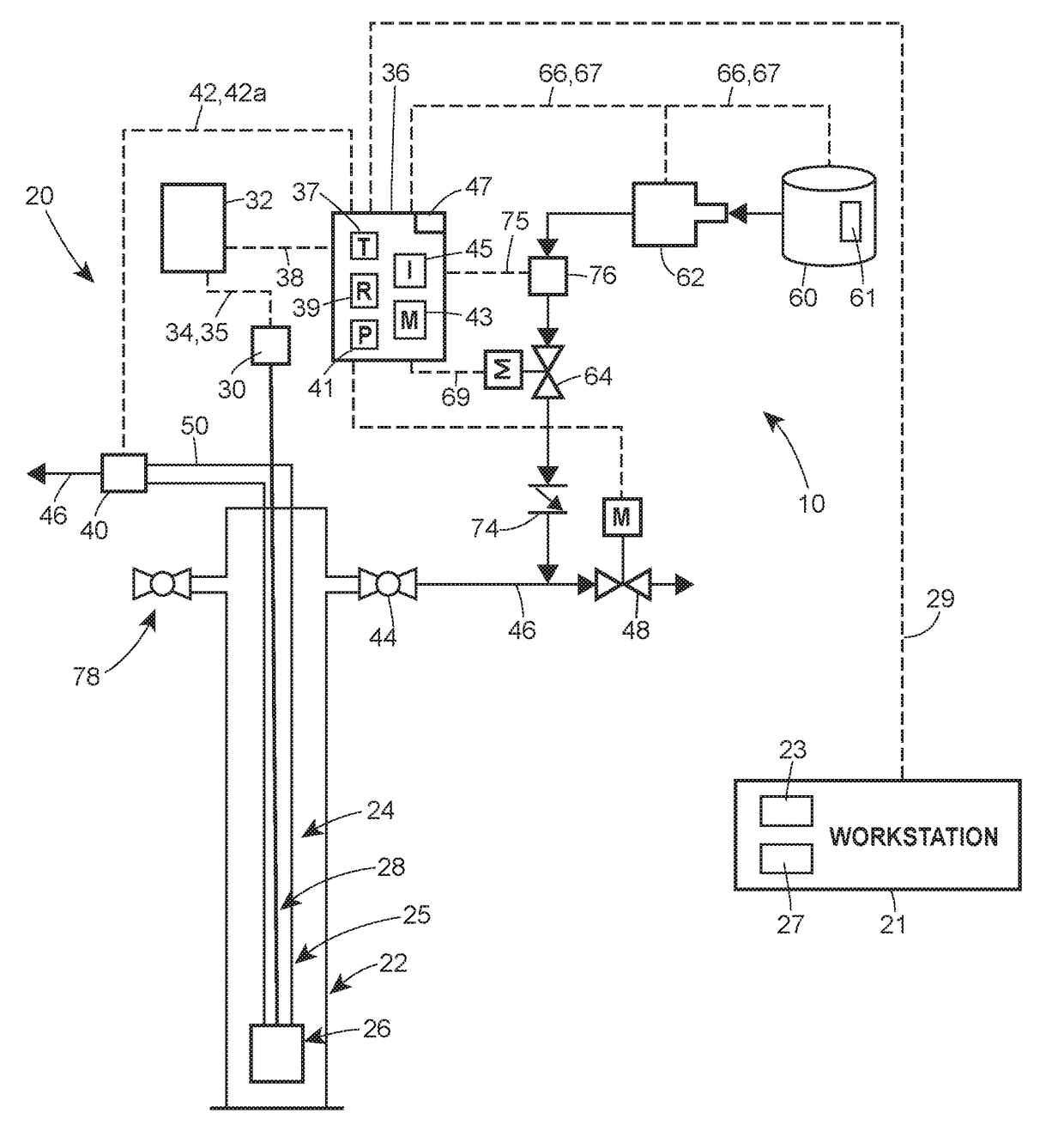
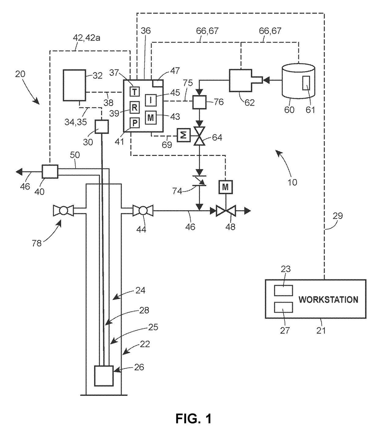
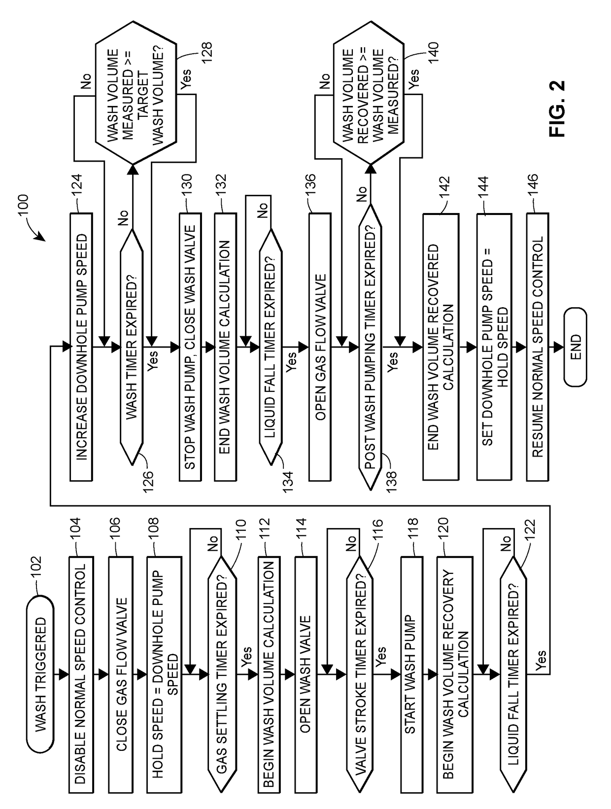
[0030]Generally, an automated wash system for use with a progressing cavity (PC) pump system is disclosed. The automated wash system includes a wash fluid source that is communicably and operatively coupled to a controller of the PC pump system, such that the wash fluid source is responsive to signals and / or commands from the controller. The automated wash system further includes a wash valve in fluid communication with the wash fluid source and an annulus of a well casing of the PC pump system. The wash valve controls the flow of wash fluid between the wash fluid source and the annulus. So configured, upon receipt of a command to initiate a wash cycle, the controller estimates an amount of wash fluid from the wash fluid source that has been injected into the annulus. The controller then automatically opens the wash valve to enable a preset amount of wash fluid from the wash fluid source to be directed into the annulus, and increases a speed of the PC pump via a signal to a motor op...


PUM


Abstract

A method of automatically washing a well casing of a progressing cavity (PC) pump system. The method includes disabling, via a controller, a normal speed control of a progressing cavity (PC) pump of the PC pump system, and closing, via the controller, a gas flow valve to stop upward fluid flow in an annulus of the well casing. The method further includes opening a wash valve to allow fluid from the wash fluid source into the well casing. Upon wash fluid accumulation within the annulus, the method further includes increasing the speed of the pump to begin flushing the well casing, and closing the wash valve.

Description

FIELD OF THE DISCLOSURE[0001]The present invention relates generally to progressing cavity pumps, and more specifically, to an automated wash system and method for use with a progressing cavity pump (PCP) system.BACKGROUND OF THE DISCLOSURE[0002]Some oil and gas wells produce sand and silt along with produced liquid. Progressing cavity pumps (PCPs) are particularly suited to these applications because they can mobilize such fluid mixtures without sustaining significant damage. Although PCPs can typically move dirty fluid through the pump, the solid material must still be conveyed all the way to the surface, which in some cases is a distance of 1000 meters or more. It has long been understood that the solid particles will be carried to the surface by the liquid as long as the upward velocity of the surrounding liquid exceeds a particular critical velocity. If the liquid velocity falls below the critical velocity, solid particles will begin to accumulate. If enough material settles in...

Claims


Application Information

Patent Timeline
IPC IPC(8): E21B37/00E21B43/12E21B47/00E21B34/02E21B47/10
CPCE21B37/00E21B43/128E21B47/0007E21B34/02E21B47/10E21B21/08E21B21/10F04C11/00F04C14/08E21B21/00E21B43/126E21B43/38F04B49/106F04B17/03F04B49/103E21B47/008E21B47/047F04B47/06G01F22/02
Inventor MILLS, THOMAS MATTHEW
Owner BRISTOL
Why Eureka
Try Eureka