Supercharge Your Innovation With Domain-Expert AI Agents!

Method for controlling the precession of a vibrating structure gyroscope

a technology of vibrating structure and gyroscope, which is applied in the direction of speed measurement using gyroscopic effects, instruments, surveying and navigation, etc., can solve the problems of reducing the estimated navigation solution, and affecting the accuracy of measurement results.

Active Publication Date: 2018-04-05
SAFRAN ELECTRONICS & DEFENSE
View PDF4 Cites 0 Cited by
  • Summary
  • Abstract
  • Description
  • Claims
  • Application Information

AI Technical Summary

Benefits of technology

The invention aims to reduce the impact of measurement errors caused by a vibrating structure gyroscope on navigation data produced by an inertial measurement unit. The invention proposes a method for generating a second control signal based on the first control signal and positioning data, which is designed to minimize accumulated angular errors in the gyroscope's measurements. This second control signal is generated dynamically and corrects the first signal in a way that reduces errors in the measurement's platform coordinate system, which is the coordinate system used after processing. The invention's technical effect is to improve the accuracy of navigation data and reduce the impact of measurement errors on navigation accuracy.

Problems solved by technology

However, the measurement of electrical angle can be riddled with errors transmitted to the estimated angle of rotation of the case of the gyroscope.
However, if the alternating precession technique allows the average of the errors in the measurement coordinate system (coordinate system of the support of the gyroscope) to be cancelled out, this technique does not allow the effect of these errors in the platform coordinate system to be cancelled out.
This leads to a degradation of the estimated navigation solution when the carrier carries out angular movements in the platform coordinate system.

Method used


Image

  • Method for controlling the precession of a vibrating structure gyroscope
  • Method for controlling the precession of a vibrating structure gyroscope
  • Method for controlling the precession of a vibrating structure gyroscope

Examples


Embodiment Construction

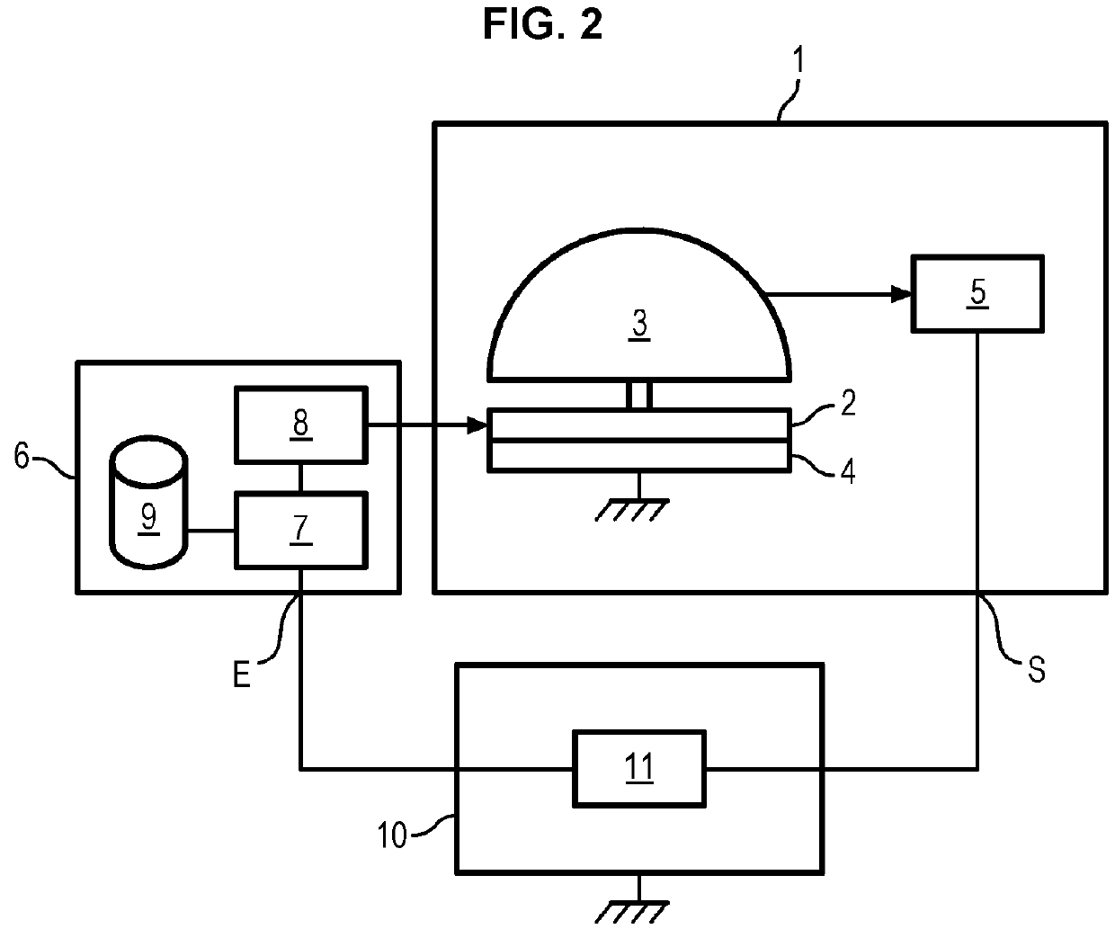
[0048]In reference to FIG. 2, a vibrating structure gyroscope 1 comprises a support 2 and a resonator 3.

[0049]The resonator is fastened onto the support, but is capable of vibrating with respect to the support 2 in the way described in relation to FIG. 1.

[0050]The resonator 3 can, for example, have a hemispherical shape, in which case it is called a hemispherical resonator gyroscope (abbreviated as HRG). The resonator 3 is suitable for vibrating in a plane of vibration corresponding to the plane shown in FIG. 1 and described in the introduction.

[0051]The gyroscope also comprises a case 4 linked to a measurement reference frame defined by a measurement coordinate system. The case 4 houses the support 2 and the resonator 3. The case 4 comprises an output S.

[0052]The vibrating structure gyroscope also comprises at least one vibration sensor 5 housed in the case 4, for example a plurality of sensors distributed about an axis normal to the plane of vibration of the resonator. The sensor ...


PUM


Abstract

A method is proposed for controlling the precession of a gyroscope (1) comprising a support (2) and a resonator (3), the support (2) being mobile in a platform coordinate system and stationary in a measurement coordinate system, the method comprising the generation (101) of a first control signal suitable for rotating the resonator (3) with respect to the support (2) in two opposite directions of rotation during a first period, the method being characterized by the following steps:reception (104) of data (Tpm) on relative positioning between the measurement coordinate system and the platform coordinate system,calculation (105) of a second control signal to be generated during a second period on the basis of the first control signal and the relative-positioning data, the second control signal being chosen in such a way as to minimize an average of accumulated angular errors in the angular measurements acquired by the gyroscope during the entirety of the first and second period, the angular errors being expressed in the platform coordinate system.

Description

GENERAL FIELD[0001]The invention relates to the field of devices of angular measurements.[0002]The invention relates more specifically to a method for controlling a vibrating structure gyroscope and a device for implementing this method.PRIOR ART[0003]A gyroscope is a device suitable for acquiring angular measurements (for examples angular positions or angular speeds).[0004]A particular type of gyroscope, called “vibrating structure gyroscope,” comprises a support and a resonator mobile with respect to the support. The resonator is configured to vibrate in a given plane, called plane of vibration.[0005]The plane of vibration of a vibrating structure gyroscope is illustrated in FIG. 1.[0006]The resonator of this gyroscope vibrates in two directions V1 and V2 that define the plane of vibration. In other words, the resonator is suitable for contracting and stretching in the direction V1 and in the direction V2 perpendicular to V1.[0007]The vibration of the gyroscope has nodes and anti-...

Claims


Application Information

Patent Timeline
IPC IPC(8): G01C25/00G01C19/5776
CPCG01C25/005G01C19/5776G01C19/567G01C19/56
Inventor DEBANNE, PASCALPINTURAUD, ARNAUDDELEAUX, BENJAMINCHARLAIX, JEAN-CHRISTOPHE
Owner SAFRAN ELECTRONICS & DEFENSE
Features
  • R&D
  • Intellectual Property
  • Life Sciences
  • Materials
  • Tech Scout
  • Unparalleled Data Quality
  • Higher Quality Content
  • 60% Fewer Hallucinations
Learn More