Imaging spectrometer with reflective grating

a spectrometer and reflective technology, applied in the field of imaging spectrometers, can solve the problems of difficult manufacture, high cost, free-form gratings, etc., and achieve the effect of compact design and convenient adaptation

Active Publication Date: 2018-04-05
EUROPEAN SPACE AGENCY
View PDF3 Cites 0 Cited by
  • Summary
  • Abstract
  • Description
  • Claims
  • Application Information

AI Technical Summary

Benefits of technology

[0012]Configured as such, the inventive imaging spectrometer based on a reflective grating can achieve a magnification value significantly different from one, both larger and smaller than one. In particular, the imaging spectrometer can achieve magnification values smaller than 0.5 and larger than two. The possibility to achieve a magnification larger than one allows to design optical instruments including the imaging spectrometer that are more compact, lighter, and smaller than comparable optical instruments using a conventional imaging spectrometer. The above design of the imaging spectrometer is very flexible and can be readily adapted to respective requirements and applications. Moreover, the imaging spectrometer can work with conventional reflective gratings (as opposed to freeform gratings, which are difficult to manufacture and therefore expensive).
[0013]In embodiments, the first and third curved reflective portions may be formed on a first reflective optical element. The first reflective optical element may be curved. Further, the first reflective optical element may be monolithically formed, i.e., be a monolithic, or integral, optical element. In other words, the first and third curved reflective portions may relate to different regions, or areas, of the same (first) optical element. Likewise, the second and fourth curved reflective portions may be formed on a second reflective optical element. The second reflective optical element may be arranged opposite the first reflective optical element. That is, the first reflective optical element (e.g., the reflective surface or side of the first reflective optical element) may face the second reflective optical element (e.g., the reflective surface or side of the second reflective optical element). The second reflective optical element may be curved. Further, the second reflective optical element may be monolithically formed, i.e., be a monolithic, or integral, optical element. In other words, the second and fourth curved reflective portions may relate to different regions, or areas, of the same (second) optical element. Configured as such, the imaging spectrometer allows to achieve a magnification value different from one with a very low number of optical elements (e.g., one grating and one mirror) and for a very compact design.

Problems solved by technology

Moreover, the imaging spectrometer can work with conventional reflective gratings (as opposed to freeform gratings, which are difficult to manufacture and therefore expensive).

Method used


Image

  • Imaging spectrometer with reflective grating
  • Imaging spectrometer with reflective grating
  • Imaging spectrometer with reflective grating

Examples


Embodiment Construction

[0034]In the following, exemplary embodiments of the disclosure will be described with reference to the appended figures. Identical elements in the figures may be indicated by identical reference numbers, and repeated description thereof may be omitted.

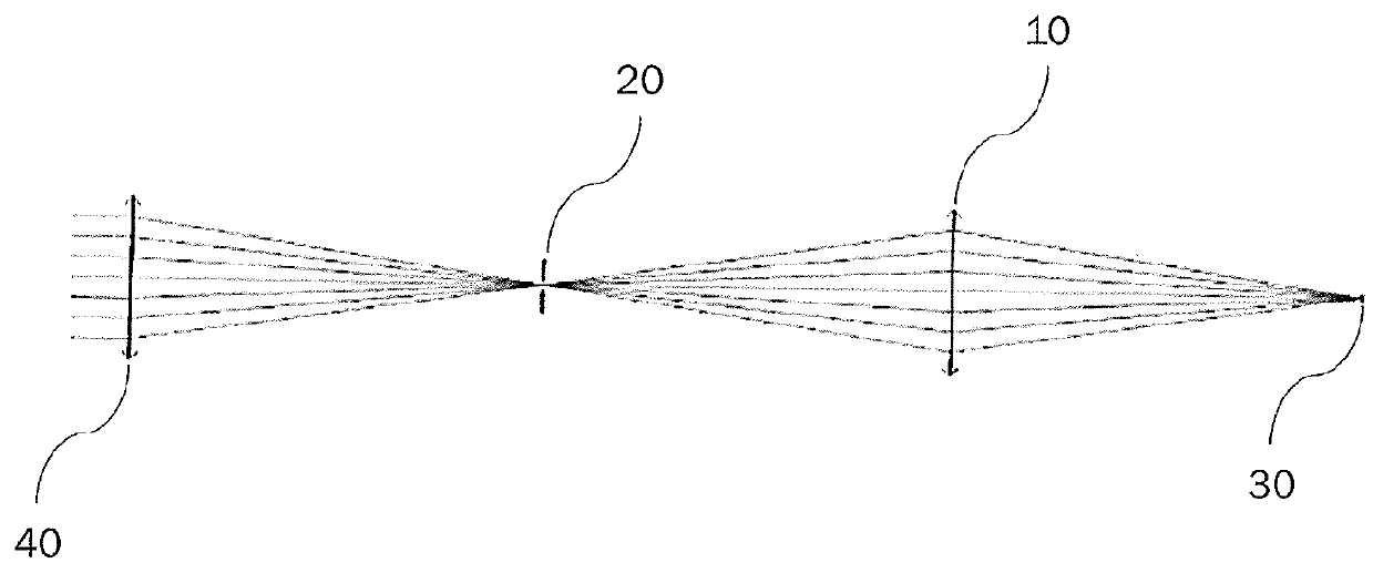
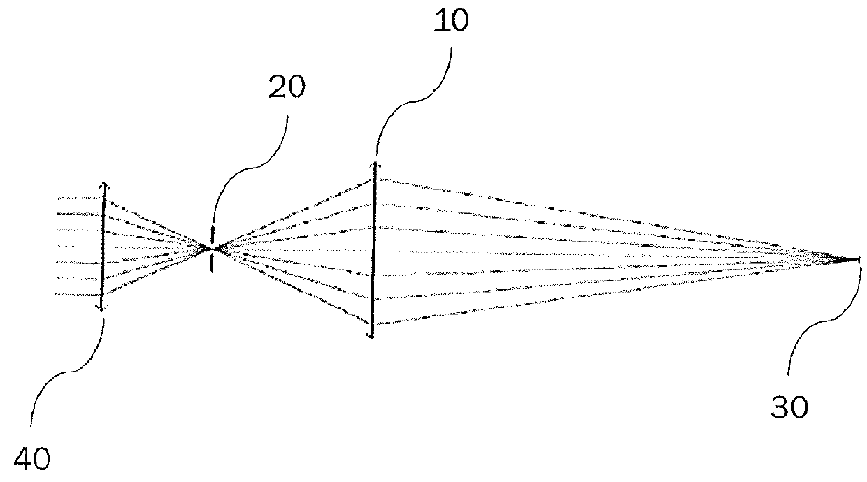
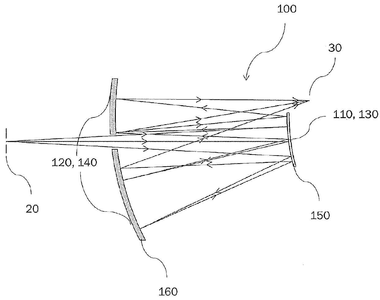
[0035]Broadly speaking, the present disclosure concerns the design and manufacture of a compact imaging spectrometer based on a reflective grating. The design is flexible and can achieve magnification values different from one. As indicated above, for some applications it may be better to have magnification lower than one (e.g., PAN sharpening), and for other applications it may be better to have magnification larger than one (e.g., design of more compact instruments). Imaging spectrometers proposed by the present disclosure allow to extend the magnification range both above and below one.

[0036]A basic design of an imaging spectrometer according to embodiments of the disclosure includes two (first and second) curved (e.g., concave or ...


PUM


Abstract

An imaging spectrometer receives a beam of light from a slit and outputs the beam of light to a focal plane. The output beam of light at the focal plane is dispersed in accordance with a spectral composition of the beam of light received from the slit. The imaging spectrometer comprises first to fourth curved reflective portions. The first to fourth curved reflective portions are arranged so that the beam of light, in its passage from the slit to the focal plane, sequentially strikes the first to fourth curved reflective portions and is reflected by the first to fourth curved reflective portions. Further, the first to fourth curved reflective portions are alternatingly concave or convex, respectively, along the passage of the beam of light. At least one of the first to fourth curved reflective portions has a reflective grating structure. Further disclosed is a method of manufacturing such imaging spectrometer.

Description

BACKGROUNDTechnical Field[0001]This application relates to imaging spectrometers and to methods for manufacturing imaging spectrometers. The application particularly relates to imaging spectrometers with a reflective grating and to methods of manufacturing such imaging spectrometers.Description of the Related Art[0002]Imaging spectrometers are important optical instruments for earth observation and science missions, for example. Many imaging spectrometer instruments are based on mirror designs with reflective gratings and most of these designs can achieve only unit magnification or magnification ratios very close to one. For some applications, the possibility to have a spectrometer with a magnification value different from one is a key factor to enable instrument designs that are compact, cost effective, and offer high performance.[0003]Optical instruments with an imaging spectrometer are normally based on the following concept: a telescope focuses light on the entrance slit of the ...

Claims


Application Information

Patent Timeline
Patent Type & Authority Applications(United States)
IPC IPC(8): G01J3/26G02B17/06G02B5/18G01J3/18G01J3/28
CPCG01J3/26G02B17/061G02B17/0615G02B5/1861G01J3/1809G01J3/2823G01J2003/262G01J3/0291G01J3/021G01J3/18G01J3/0208
Inventor TACCOLA, MATTEO
Owner EUROPEAN SPACE AGENCY
Why Eureka
Try Eureka