Port interface for a pneumatic distribution system

Active Publication Date: 2018-04-12
CNH IND CANADA
View PDF2 Cites 1 Cited by
  • Summary
  • Abstract
  • Description
  • Claims
  • Application Information

AI Technical Summary

Benefits of technology

[0004]In another embodiment, a port interface for a pneumatic distribution system includes a body and a first flow passage extending through the body. The first flow passage is configured to receive fluidized particulate material from an outlet port of a header and to output the fluidized particulate material to an outlet line. The port interface also includes a second flow passage extending through the body. The second flow passage is configured to receive a balancing airflow and to output the balancing airflow to an external environment. In addition, the port interface includes a valve at least par

Problems solved by technology

Unfortunately, if a portion of the seeding implement passes over a region of the field that has already received the particulate material, the region may receive more particulate m

Method used


Image

  • Port interface for a pneumatic distribution system
  • Port interface for a pneumatic distribution system
  • Port interface for a pneumatic distribution system

Examples


Example

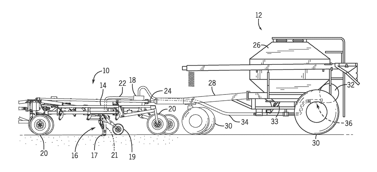
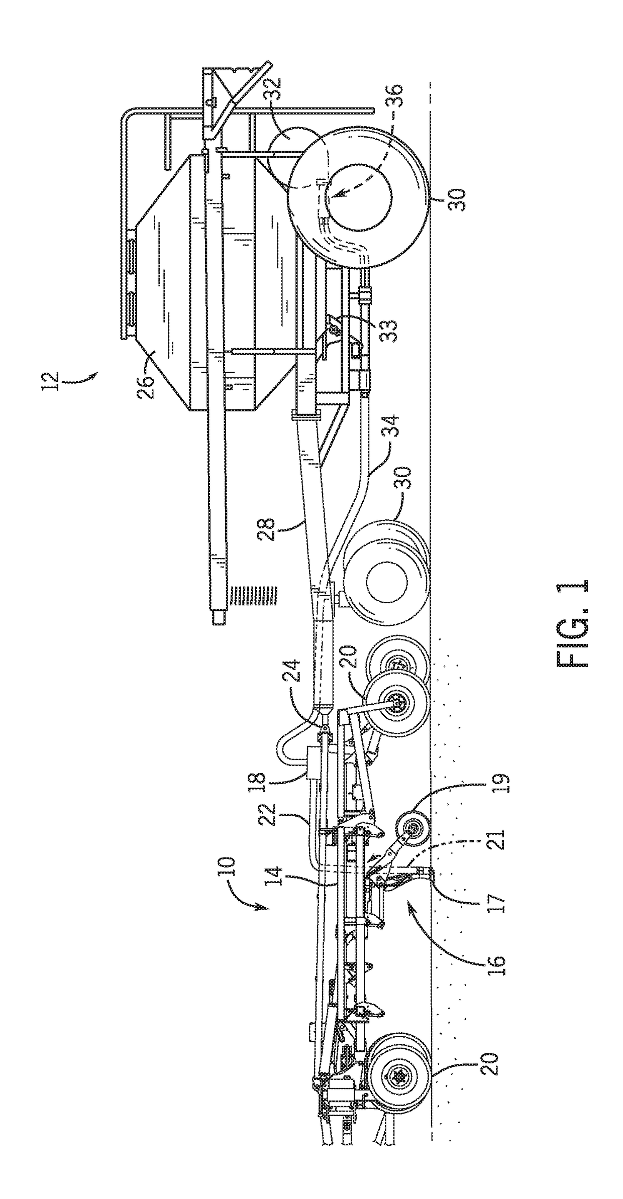
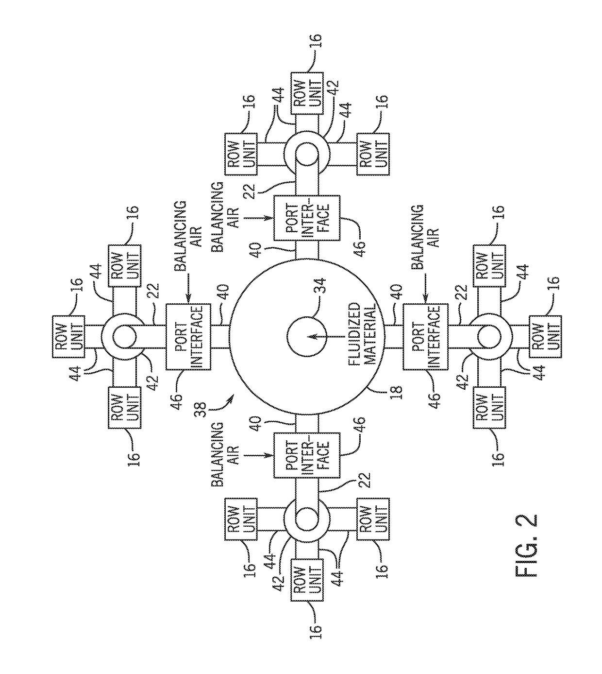
[0012]Certain agricultural implements (e.g., seeding implements) may distribute a particulate material (e.g., seeds, fertilizer, etc.) to multiple row units (e.g., ground engaging opener assemblies). Additionally, each row unit may engage the ground to excavate a trench into soil, and each row unit may deposit the particulate material into the trench. In this manner, rows of the particulate material may be established throughout a field. The particulate material may include any suitable product / material that is desired to be deposited into the soil, such as various types of seeds and fertilizers.

[0013]Generally, each row unit does not provide adjustable control over the deposition of the particulate material. Instead, each row unit may receive fluidized particulate material via a respective pneumatic line. In addition, the row unit may enable received particulate material to drop into the trench via gravity. Accordingly, the rate at which particulate material is deposited into the s...


PUM


Abstract

A port interface for a pneumatic distribution system includes a first flow passage configured to receive fluidized particulate material from an outlet port of a header and to output the fluidized particulate material to an outlet line. The port interface also includes a second flow passage configured to receive a balancing airflow and to output the balancing airflow to an external environment. In addition, the port interface includes a knife valve having a blade with an opening. The blade is configured to move between a first position in which the opening is substantially aligned with the first flow passage and a solid portion of the blade is substantially aligned with the second flow passage, and a second position in which the opening is substantially aligned with the second flow passage and the solid portion of the blade is substantially aligned with the first flow passage.

Description

BACKGROUND[0001]The present disclosure relates generally to a port interface for a pneumatic distribution system.[0002]Generally, agricultural seeding implements are towed behind a work vehicle, such as a tractor. These seeding implements typically include multiple row units (e.g., ground engaging opener assemblies) that excavate trenches into soil and deposit particulate material, such as seeds and / or fertilizer, into the trenches. In this manner, rows of the particulate material may be established throughout a field. For example, the particulate material may be stored in a central location, such as in a storage tank of an air cart, and distributed to each of the row units for deposition into the soil. Unfortunately, if a portion of the seeding implement passes over a region of the field that has already received the particulate material, the region may receive more particulate material than desired. As a result, the crop yield within the region may be reduced and / or particulate ma...

Claims


Application Information

Patent Timeline
IPC IPC(8): A01C7/08
CPCA01C7/082A01C7/084A01C7/088
Inventor THOMPSON, DENNIS GEORGE
Owner CNH IND CANADA
Why Eureka
Try Eureka