Installation systems and methodology for helical strake fins

a technology of helical strake fins and installation systems, which is applied in the direction of drilling casings, drilling pipes, underwater drilling, etc., can solve the problems of slow and unsafe installation, significant ocean current management in oil and gas exploration and production, and the suspension of drilling, so as to achieve quick and precise installation of the fins

Active Publication Date: 2018-04-12
VIV SOLUTIONS
View PDF4 Cites 2 Cited by
  • Summary
  • Abstract
  • Description
  • Claims
  • Application Information

AI Technical Summary

Benefits of technology

[0005]The present invention is directed to an installation assembly, such as a machine, and methods of, installing helical strake fins around a pipe directly without a shell present. The machine is configured to allow for quick and precise installation of the fins. In one embodiment, installation assembly may include an outer ring member dimensioned to encircle an underlying tubular and an inner ring member positioned concentrically inward from the outer ring member. The inner ring member is configured to rotate with respect to at least one of the outer ring member or the tubular as the outer ring member moves axially along the tubular. The apparatus may further include a fin guide configured to receive a fin and helically position the fin along the tubular as the inner ring member rotates.

Problems solved by technology

A difficult obstacle associated with the exploration and production of oil and gas is management of significant ocean currents.
VIV can cause substantial fatigue damage to the tubular or cause suspension of drilling due to increased deflections.
Both helical strakes and fairings can provide sufficient VIV suppression, but can be slow and unsafe to install.
However, it is difficult to align the pitch of each of the fins quickly and / or precisely without using measuring tools which can substantially slow down the installation.

Method used


Image

  • Installation systems and methodology for helical strake fins
  • Installation systems and methodology for helical strake fins
  • Installation systems and methodology for helical strake fins

Examples


Embodiment Construction

[0030]In this section we shall explain several preferred embodiments with reference to the appended drawings. Whenever the shapes, relative positions and other aspects of the parts described in the embodiments are not clearly defined, the scope of the embodiment is not limited only to the parts shown, which are meant merely for the purpose of illustration. Also, while numerous details are set forth, it is understood that some embodiments may be practiced without these details. In other instances, well-known structures and techniques have not been shown in detail so as not to obscure the understanding of this description.

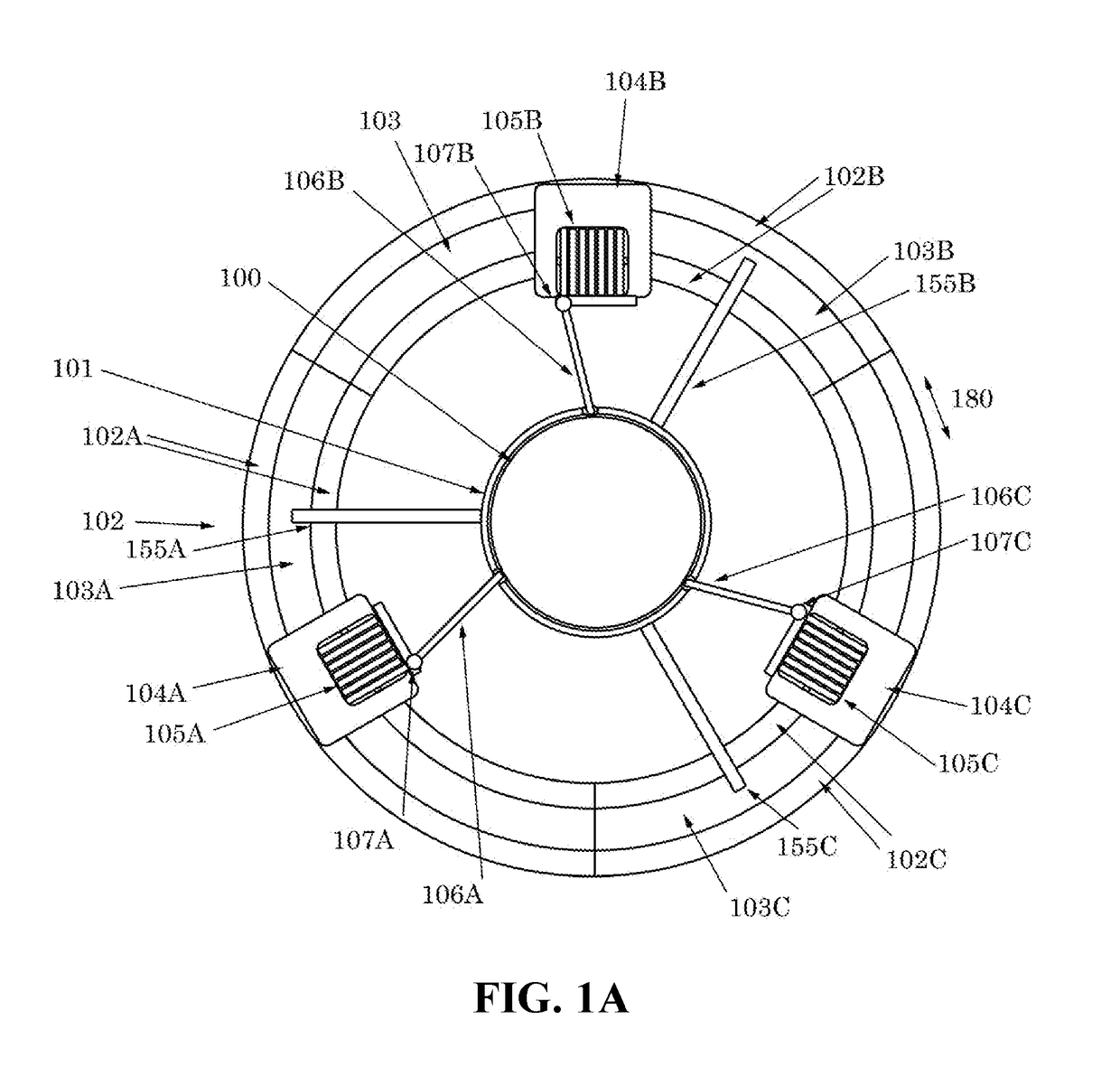
[0031]Referring now to the invention in more detail, FIG. 1A illustrates a top view of a reeled installation system turning ring. The turning ring 103 is made up of three sections 103A, 103B, and 103C that are contained in ring housing 102 which is also made up of three sections 102A, 102B, and 102C. Each of ring sections 103A-103C and housing sections 102A-102C may ...


PUM


Abstract

An apparatus and method for helically installing a vortex-induced vibration (VIV) suppression fin about a tubular. The apparatus may include an outer ring member dimensioned to encircle an underlying tubular and an inner ring member positioned concentrically inward from the outer ring member. The inner ring member is configured to rotate with respect to at least one of the outer ring member or the tubular as the outer ring member moves along the tubular. The apparatus may further include a fin guide configured to receive a fin and helically position the fin along the tubular as the inner ring member rotates. A method of installing a vortex-induced vibration (VIV) suppression fin about a tubular may include removably attaching a VIV suppression fin to an installation member. The installation member may be positioned along a tubular and moved about the tubular to helically position the fin around the tubular.

Description

CROSS-REFERENCE TO RELATED APPLICATION[0001]The application is a continuation of co-pending U.S. patent application Ser. No. 13 / 841,720, filed Mar. 15, 2013, which application claims the benefit of the earlier filing date of U.S. Provisional Patent Application No. 61 / 729,564, filed Nov. 24, 2012, the disclosures of which are incorporated herein by reference.BACKGROUND OF THE INVENTION[0002]A difficult obstacle associated with the exploration and production of oil and gas is management of significant ocean currents. These currents can produce vortex-induced vibration (VIV) and / or large deflections of tubulars associated with drilling and production. VIV can cause substantial fatigue damage to the tubular or cause suspension of drilling due to increased deflections. Both helical strakes and fairings can provide sufficient VIV suppression, but can be slow and unsafe to install.[0003]Most helical strakes consist of one or more fins that are attached to a shell, often with the fins molde...

Claims


Application Information

Patent Timeline
Patent Type & Authority Applications(United States)
IPC IPC(8): E21B7/12E21B41/00
CPCE21B41/0007E21B7/12E21B17/01E21B19/22
Inventor ALLEN, DONALD WAYNEDEHNE, JULIE ANNWEST, WILLIAM ANDREW
Owner VIV SOLUTIONS
Why Eureka
Try Eureka