Glenoid cavity bone preparation set for setting a shoulder prosthesis, and method for implanting a shoulder prosthesis

a technology for glenoid cavity and set, which is applied in the field of glenoid cavity bone preparation set for setting a shoulder prosthesis, can solve the problems of long, difficult, and laborious bone preparation of the glenoid cavity, and achieve the effect of facilitating the realization of the bone housing

Active Publication Date: 2018-04-19
FH ORTHO +3
View PDF0 Cites 15 Cited by
  • Summary
  • Abstract
  • Description
  • Claims
  • Application Information

AI Technical Summary

Benefits of technology

[0015]Such a configuration of the drill guide, and in particular the presence of the passage orifice, allows guaranteeing an optimum positioning of the drill guide with respect to the guide pin, and therefore with respect to the concave surface which has been prepared beforehand in the glenoid cavity, and facilitating and securing the realization of the bone bores in the glenoid cavity using at least one drill bit guided by the first and second guide orifices. Thus, the drill guide according to the present invention allows realizing, easily and accurately, the first removals of bone material of the glenoid cavity, and this strictly within the bulk of the anchoring element of the glenoid base.
[0016]Furthermore, the configuration of the compactor, and in particular the presence of the passage hole, guarantees an optimum positioning of the compactor with respect to the guide pin, and therefore with respect to the concave surface which has been prepared beforehand in the glenoid cavity, and therefore facilitates the realization of the bone housing by compacting the cancellous bone of the glenoid cavity.

Problems solved by technology

However, such a configuration of the anchoring element implies a bone preparation of the glenoid cavity which is complex, risky, long and tedious, and which involves the dexterity of the surgeon.

Method used


Image

  • Glenoid cavity bone preparation set for setting a shoulder prosthesis, and method for implanting a shoulder prosthesis
  • Glenoid cavity bone preparation set for setting a shoulder prosthesis, and method for implanting a shoulder prosthesis
  • Glenoid cavity bone preparation set for setting a shoulder prosthesis, and method for implanting a shoulder prosthesis

Examples


Embodiment Construction

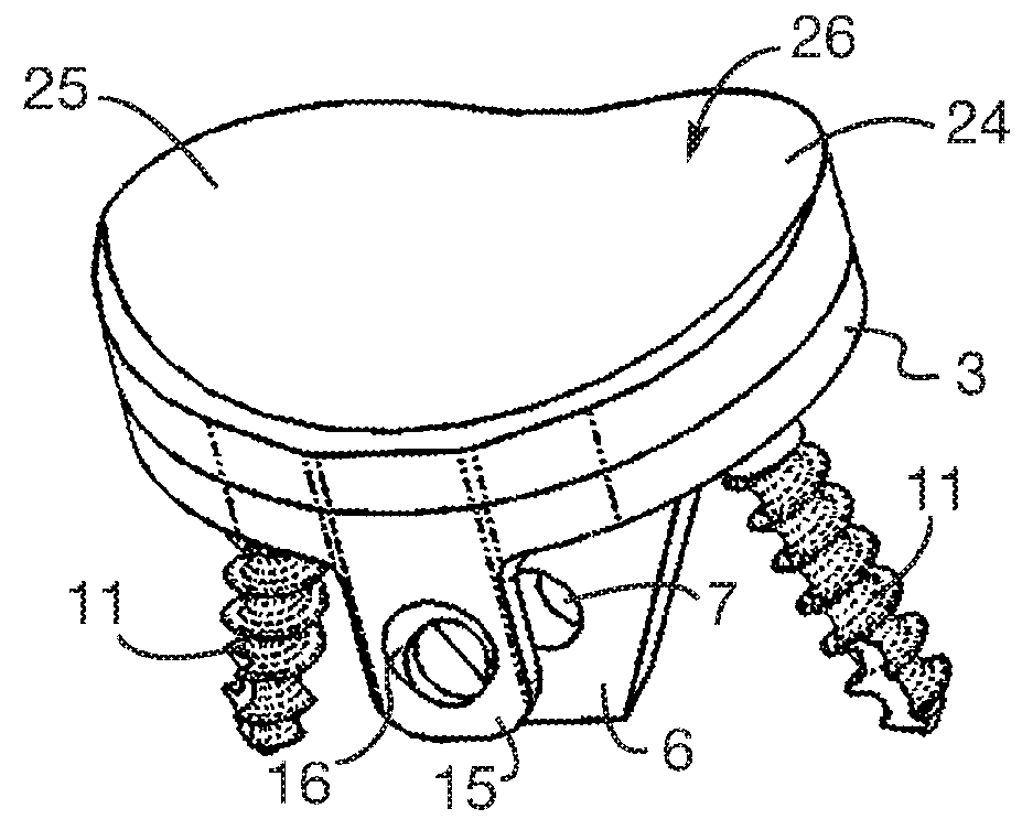
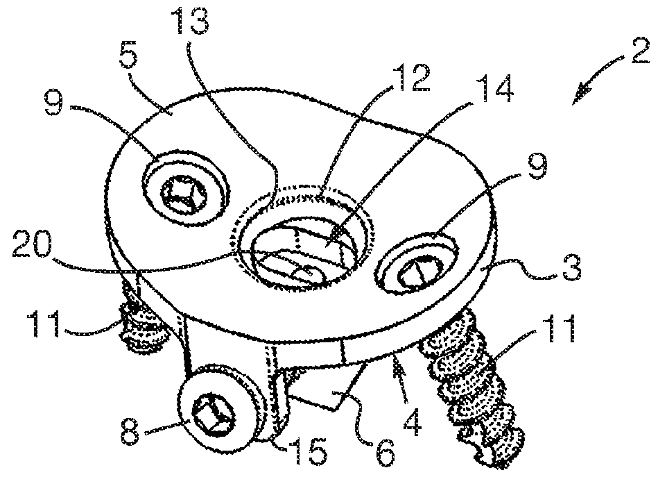
[0093]FIG. 1 represents a glenoid base 2 configured to be fastened on a glenoid cavity of a scapula which has been prepared beforehand. The glenoid base 2 includes a support portion 3 having a generally tray-like shape. More particularly, the support portion 3 includes a bearing face 4 intended to bear against the glenoid cavity, and a support face 5 opposite to the bearing face 4 and on which an insert is intended to be fastened which is capable of cooperating with a humeral head or with a humeral implant. According to the embodiment represented in the figures, the bearing face 4 is convex and the support face 5 is concave.

[0094]The glenoid base 2 further includes an anchoring element 6, made, for example, in the form of an anchoring stud, extending from the bearing face 4 and along an extension direction. The anchoring element 6 is intended to be anchored in a bone housing formed beforehand in the glenoid cavity 3. The anchoring element 6 has a generally trapezoidal shape, and mor...


PUM


Abstract

This preparation set comprises a drill guide (31) comprising a bearing surface (33) intended to bear against a glenoid cavity, a passage orifice (35) intended for the passage of a guide pin (36) implanted in the glenoid cavity, and first and second guide orifices (37, 38) each opening into the bearing surface (33) and each intended to guide a drill bit (38) capable of realizing a bone bore in the glenoid cavity, the first and second guide orifices (37, 38) being inclined with respect to the extension axis of the passage orifice (35) and converging in the direction of the bearing surface (33); and a compactor (42) comprising a compaction portion (45) having a generally trapezoidal shape and intended to be impacted against the glenoid cavity so as to form a bone housing in the glenoid cavity, the compactor (42) further including a passage hole (49) extending at least partially in the compaction portion (45) and intended for the passage of the guide pin (36) implanted in the glenoid cavity.

Description

TECHNICAL FIELD[0001]The present invention concerns a glenoid cavity bone preparation set for setting a shoulder prosthesis, and more particularly for setting a glenoid base of such a prosthesis.BACKGROUND[0002]Conventionally, a glenoid base for a shoulder prosthesis with cementless fastening, comprises:[0003]a support portion configured to be fastened, by means of bone anchoring screws, on a glenoid cavity of a scapula which has been prepared beforehand, the support portion comprising a bearing face intended to bear against the glenoid cavity, and a support face opposite to the bearing face and on which an insert, which is capable of cooperating with a humeral head or with a humeral implant, is intended to be fastened, and[0004]an anchoring element, also called anchoring keel or stud, extending from the bearing face and intended to be anchored in a bone housing which has been formed beforehand in the glenoid cavity.[0005]Advantageously, the anchoring element has a trapezoidal shape...

Claims


Application Information

Patent Timeline
Patent Type & Authority Applications(United States)
IPC IPC(8): A61B17/17A61B17/88A61F2/46A61F2/30A61F2/40
CPCA61B17/1778A61B17/8897A61F2/4081A61F2/30749A61F2/4612A61B17/1615A61B17/1659A61B17/1684A61B17/92A61B2090/033
Inventor ROUYER, GUILLAUMEHOFFMANN, JAMESMILLER, BRUCE
Owner FH ORTHO
Why Eureka
Try Eureka