
Eureka
For R&D, Eureka makes reading and utilizing patents & technical documents easy.
Eureka AIR
Designed for self-driven R&D workflows. Generate viable solutions, solve complex R&D challenges, empower your innovation with AI.

Eureka Materials
Designed for material experts only. Revolutionize your material R&D, from search, analyze, to developing new materials.

TechResearch
Generate reliable direction feasibility study reports for your R&D in just a few steps.

TechSeek
Discover and master advanced knowledge NOW. Basics, ideas, possibilities, all at once.

TechMind
As an expert in R&D Theories, TechMind can generates customized viable solutions instantly.

TechRisk
Analyze your overall solution with one click, know your potential R&D risks in advance.

TechMonitor
Get weekly tech updates, stay abreast of the latest tech innovations and key insights.
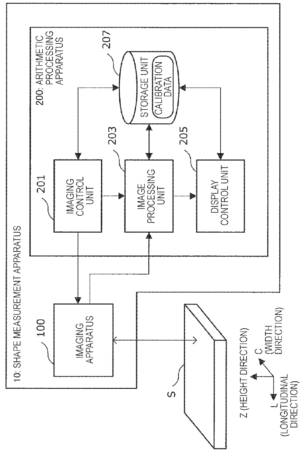
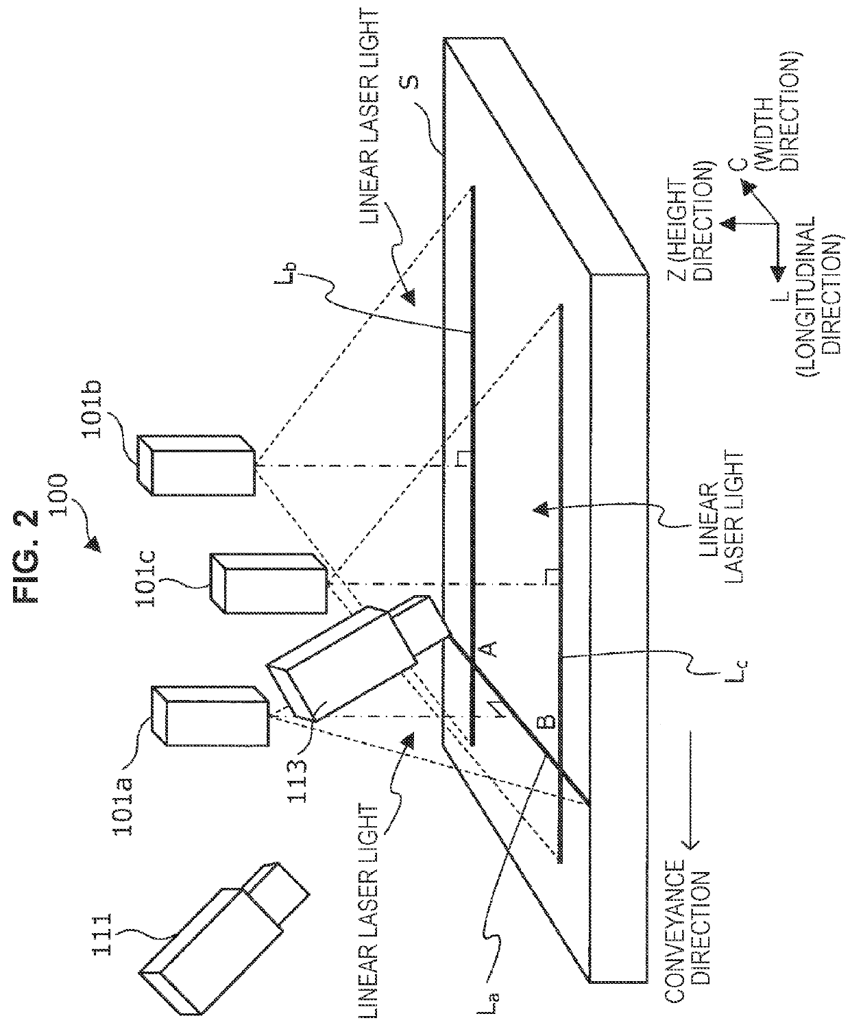
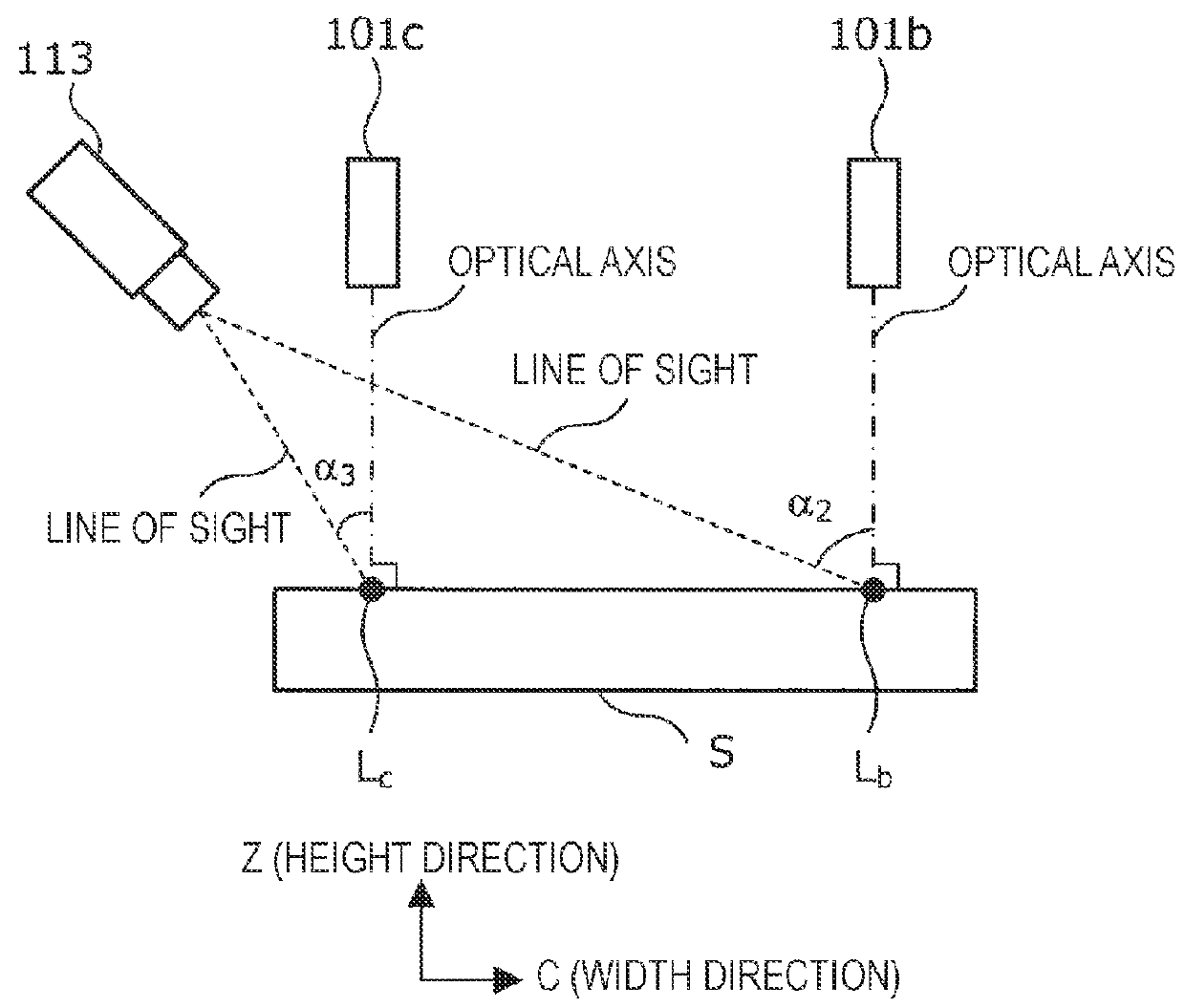
Shape measurement apparatus and shape measurement method
- Summary
- Abstract
- Description
- Claims
- Application Information
AI Technical Summary
Benefits of technology
Problems solved by technology
Method used
Image

Examples
example 1
[0274]In Example 1, translation in the Z-direction like that shown in FIG. 31A was added as disturbance during the conveyance of the aluminum sheet. The positions of the light-section lines are as shown in FIG. 31B. As a result, as shown in FIG. 31C, it can be seen that changes in the Z-axis direction due to the disturbance have been superimposed in Z(i, Xa), and the surface height of the corresponding portion is not flat. This result indicates that Z(i, Xa) has failed to express an accurate surface height. On the other hand, as shown in FIG. 31D, it has been found that Zout(i, Xa) (i=1, 2, . . . , 60) is flat and an accurate surface height has been measured.
example 2
[0275]In Example 2, rotation around the L-axis like that shown in FIG. 32A (the rotation axis was set to the center position in the width direction of the aluminum sheet, and the positive direction of the rotation angle was set to clockwise along the positive direction of the L-axis) was added as disturbance during the conveyance of the aluminum sheet. The positional relationship between the positions of the light-section lines and the rotation axis is as shown in FIG. 32B. As a result, as shown in FIG. 32C, it can be seen that changes in the Z-axis direction due to the rotation around the L-axis have been superimposed in Z(i, Xa), and the surface height of the corresponding portion is not flat. This result indicates that Z(i, Xa) has failed to express an accurate surface height. On the other hand, as shown in FIG. 32D, it has been found that Zout(i, Xa) (i=1, 2, . . . , 60) is flat and an accurate surface height has been measured.
example 3
[0276]In Example 3, rotation around the C-axis like that shown in FIG. 33A (the rotation axis was set to the center position in the longitudinal direction of the aluminum sheet, and the positive direction of the rotation angle was set to clockwise along the positive direction of the C-axis) was added as disturbance during the conveyance of the aluminum sheet. The positional relationship between the positions of the light-section lines and the rotation axis is as shown in FIG. 33B. As a result, as shown in FIG. 33C, it can be seen that changes in the Z-axis direction due to the rotation around the C-axis have been superimposed in Z(i, Xa), and the surface height of the corresponding portion is not flat. This result indicates that Z(i, Xa) has failed to express an accurate surface height. On the other hand, as shown in FIG. 33D, it has been found that Zout(i, Xa) (i=1, 2, . . . , 60) is flat, and an accurate surface height has been measured.
[0277]The preferred embodiment(s) of the pre...
PUM
 Abstract
Description
Claims
Application Information
 - R&D Engineer
- R&D Manager
- IP Professional
- Industry Leading Data Capabilities
- Powerful AI technology
- Patent DNA Extraction
Browse by: Latest US Patents, China's latest patents, Technical Efficacy Thesaurus, Application Domain, Technology Topic, Popular Technical Reports.
© 2024 PatSnap. All rights reserved.Legal|Privacy policy|Modern Slavery Act Transparency Statement|Sitemap|About US| Contact US: help@patsnap.com