Differential type magnetic sensor
a magnetic sensor and different type technology, applied in the field of magnetic sensors, can solve the problems of inability to distinguish the background magnetic field from 1 nt of the magnetic field components of iron powder, and disadvantageous increase in production costs
- Summary
- Abstract
- Description
- Claims
- Application Information
AI Technical Summary
Benefits of technology
Problems solved by technology
Method used
Image

Examples
embodiment 1
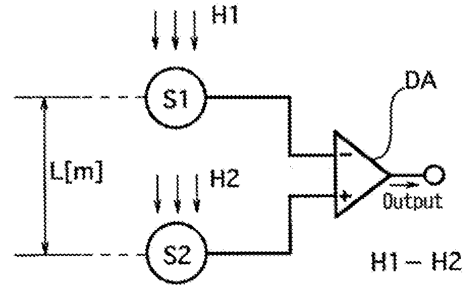
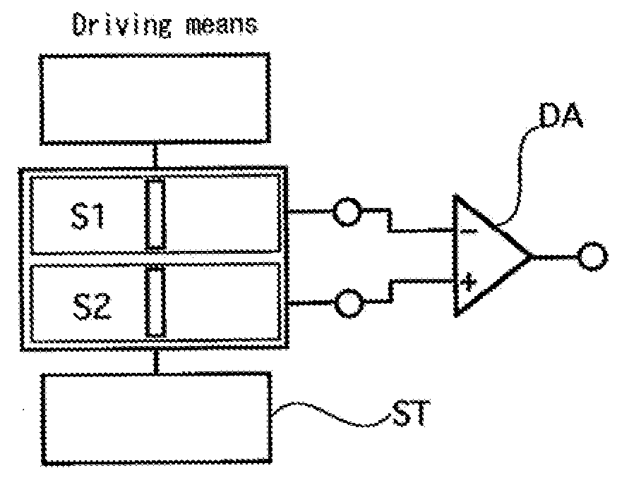
[0029]A differential type magnetic sensor of a first embodiment comprises, as shown in FIG. 2, two magnetic detecting means S1 and S2 including magneto-impedance elements having amorphous wires serving as two magneto-sensitive bodies and a differential operating means DA, and in the differential type magnetic sensor which outputs a signal of a difference between magnetic fields at two different points, a signal adjusting means ST is provided which adjusts the output signal such that when the external magnetic field intensities are equal, magnetic field signal voltages of the same magnitude axe output between the magnetic detecting means S1 and S2 and the differential operating means DA in response to a difference between the detection sensitivities on the amorphous wires of the two magneto-impedance elements.
[0030]In the differential type magnetic sensor of the first embodiment configured as described above, since the signal adjusting means ST adjusts the signal in response to the d...
embodiment 2
[0031]In a differential type magnetic sensor of a second embodiment, according to the first embodiment, as shown in FIG. 3, the two magneto-impedance sensors S1 and S3 include the magneto-impedance elements E1 and E2 formed with the amorphous wires and a driving circuit DC for outputting a pulse current, and resistance circuits r1 and r2 serving as the signal adjusting means ST are inserted between the magneto-impedance elements E1 and E2 and the driving circuit DC such that the products of the detection sensitivities or the magneto-impedance elements E1 and E2 and the driving currents applied to the respective magneto-impedance elements are substantially equal to each other.
[0032]In the differential type magnetic sensor of the second embodiment configured as described above, since the resistance values of the resistance circuits r1 and r2 inserted into the driving circuit DC are set such that a driving current in response to a ratio of the detection sensitivities on the two magneto...
embodiment 3
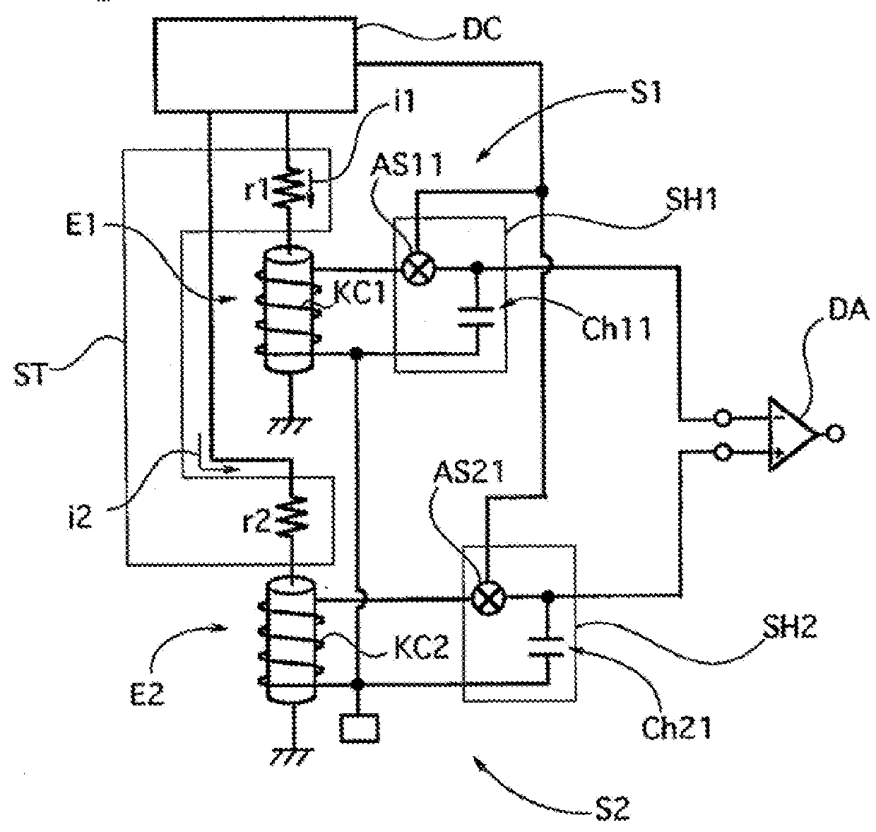
[0033]In a differential type magnetic sensor of a third embodiment, as shown in FIG. 4, the two magneto-impedance sensors S1 and S2 include the sample-hold circuits SH1 and SH2 including amplification circuits A1 and A2, a resistance circuit (unillustrated) is inserted as the signal adjusting means ST such that the products of the detection sensitivities on the magneto-impedance elements E1 and E2 formed with the respective magneto-sensitive bodies and the gains of the sample-hold circuits SH1 and SH2 serving as the signal processing means connected to the respective magneto-impedance elements are substantially equal to each other and thus the amplification degrees of the amplification circuits A1 and A2 in the sample-hold circuits SH1 and SH2 are set.
[0034]In the differential type magnetic sensor of the third embodiment configured as described above, since the amplification degrees of the amplification circuits A1 and A2 in the sample-hold circuits SH1 and SH2 are set in response t...
PUM
 Abstract
Description
Claims
Application Information
 - R&D
- Intellectual Property
- Life Sciences
- Materials
- Tech Scout
- Unparalleled Data Quality
- Higher Quality Content
- 60% Fewer Hallucinations
Browse by: Latest US Patents, China's latest patents, Technical Efficacy Thesaurus, Application Domain, Technology Topic, Popular Technical Reports.
© 2025 PatSnap. All rights reserved.Legal|Privacy policy|Modern Slavery Act Transparency Statement|Sitemap|About US| Contact US: help@patsnap.com