Method for manufacturing multilayer ceramic capacitor

a multi-layer ceramic and capacitor technology, applied in the direction of fixed capacitors, stacked capacitors, fixed capacitor details, etc., can solve the problems of electrode-end cracking, peeling of the outer electrode from the multi-layer body, and increased temperature, so as to reduce the stress of the outer electrodes on the multi-layer body and increase the temperature. the effect of increasing the temperatur

Active Publication Date: 2018-04-19
MURATA MFG CO LTD
View PDF0 Cites 12 Cited by
  • Summary
  • Abstract
  • Description
  • Claims
  • Application Information

AI Technical Summary

Benefits of technology

[0005]Accordingly, preferred embodiments of the present invention provide methods for manufacturing multilayer ceramic capacitors wherein there is no cause for concern that electrode peeling and electrode-end cracking may occur.
[0012]According to a method for manufacturing a multilayer ceramic capacitor of a preferred embodiment of the present invention, a rate of temperature increase is increased in a section in which shrinkage of Ni is significant in the firing step and, thus, the shrinkage time of the conductive paste and the shrinkage time of the multilayer body are similar to each other. Consequently, there is no cause for concern that electrode peeling and electrode-end cracking may occur because the stress from the outer electrodes on the multilayer body is reduced.

Problems solved by technology

When the conductive paste containing Ni as a primary component to form the outer electrodes, and the multilayer body including dielectric ceramic layers are fired at the same time, shrinkage of Ni occurs prior to shrinkage of the multilayer body because the sintering temperature of Ni is 800° C. and the sintering temperature of the multilayer body is 1,100° C. Consequently, stress is generated between the multilayer body and the outer electrodes, and electrode peeling of the outer electrode from the multilayer body and electrode-end cracking may occur.

Method used


Image

  • Method for manufacturing multilayer ceramic capacitor
  • Method for manufacturing multilayer ceramic capacitor
  • Method for manufacturing multilayer ceramic capacitor

Examples


experimental example 1

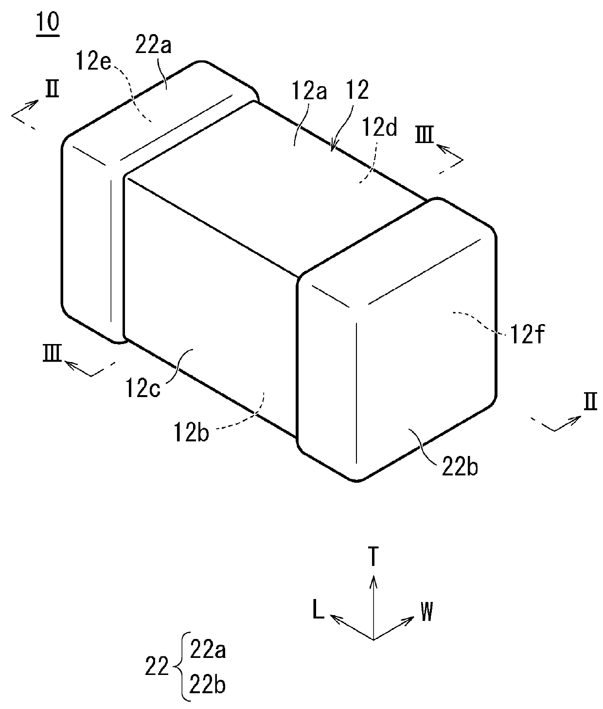
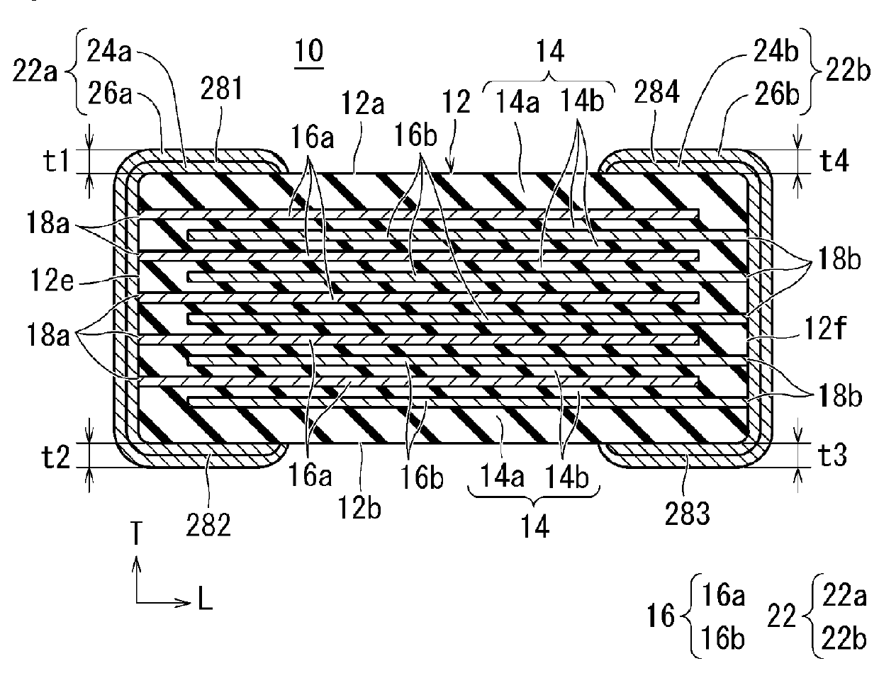
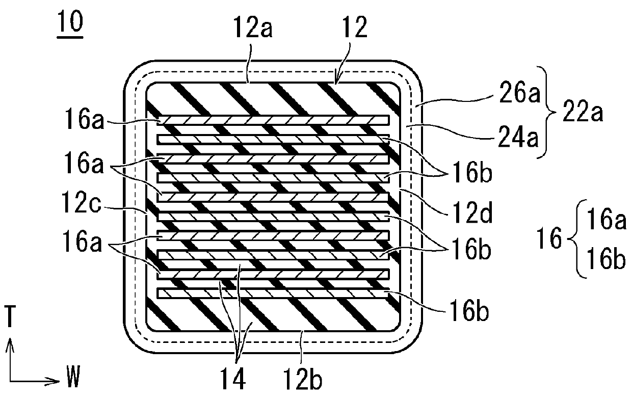
[0053]A multilayer ceramic capacitor 10 was used. The dimension in the length direction L of the multilayer ceramic capacitor was about 1.05 mm, the dimension in the width direction W was about 0.65 mm, and the dimension in the stacking direction T was about 0.65 mm, the primary component of the dielectric layer 14 was BaTiO3, the inner electrode layer 16 contained Ni, and the outer electrode 22 was a Ni co-sintered electrode produced by applying a conductive paste, which contained Ni as a primary component, in which the common material was BaTiO3, and in which the content of the common material was about 30 percent by weight, to the multilayer body and performing sintering at the same time with the common material.

[0054]Evaluation was performed by using a sample in which the average maximum thickness of the outer electrode extending portion after firing was about 15 μm. The e-dimension after firing of the sample used was about 210 μm.

TABLE 1Rate of temperatureincreasefrom 800° C. t...

experimental example 2

[0058]A multilayer ceramic capacitor 10 was used. The dimension in the length direction L of the multilayer ceramic capacitor was about 0.65 mm, the dimension in the width direction W was about 0.35 mm, and the dimension in the stacking direction T was about 0.35 mm, the primary component of the dielectric layer 14 was BaTiO3, the inner electrode layer 16 contained Ni, and the outer electrode 22 was a Ni co-sintered electrode produced by applying a conductive paste, which contained Ni as a primary component, in which the common material was BaTiO3, and in which the content of the common material was about 30 percent by weight, to the multilayer body and performing sintering at the same time with the common material.

[0059]Evaluation was performed by using a sample in which the average maximum thickness of the outer electrode extending portion after firing was about 15 μm. The e-dimension after firing of the sample used was about 210 μm.

[0060]The firing profile was the same as that in...

experimental example 3

[0061]A multilayer ceramic capacitor 10 was used. The dimension in the length direction L of the multilayer ceramic capacitor was about 1.05 mm, the dimension in the width direction W was about 0.65 mm, and the dimension in the stacking direction T was about 0.65 mm, the primary component of the dielectric layer 14 was BaTiO3, the inner electrode layer 16 contained Ni, and the outer electrode 22 was a Ni co-sintered electrode produced by applying a conductive paste, which contained Ni as a primary component, in which the common material was BaTiO3, and in which the content of the common material was about 30 percent by weight, to the multilayer body and performing sintering at the same time with the common material.

[0062]Evaluation was performed by using a sample in which the average maximum thickness of the outer electrode extending portion after firing was about 18 μm. The e-dimension after firing of the sample used was about 210 μm.

[0063]The firing profile was the same as that in...


PUM

PropertyMeasurementUnit
temperatureaaaaaaaaaa
thicknessaaaaaaaaaa
lengthaaaaaaaaaa

Abstract

A method for manufacturing a multilayer ceramic capacitor includes preparing a green multilayer body including a stack of dielectric sheets printed with inner electrodes, coating the green multilayer body with a conductive paste that is connected to the inner electrodes, and firing the conductive paste and the green multilayer body at the same time, wherein a rate of temperature increase from about 800° C. to about 1,100° C. during the firing is about 15° C. per minute or more.

Description

CROSS REFERENCE TO RELATED APPLICATIONS[0001]This application claims the benefit of priority to Japanese Patent Application No. 2016-203446 filed on Oct. 17, 2016. The entire contents of this application are hereby incorporated herein by reference.BACKGROUND OF THE INVENTION1. Field of the Invention[0002]The present invention relates to a method for manufacturing a multilayer ceramic capacitor including a multilayer body, in which a plurality of dielectric layers and a plurality of inner electrode layers are stacked, and outer electrodes disposed on the end surfaces of the multilayer body so as to be electrically connected to the inner electrode layers.2. Description of the Related Art[0003]A multilayer ceramic capacitor includes a multilayer body, in which dielectric layers and inner electrode layers are alternately stacked. Pairs of the inner electrode layers are disposed so as to be alternately exposed at the respective opposing end surfaces of the multilayer body. The multilayer...

Claims


Application Information

Patent Timeline
Patent Type & Authority Applications(United States)
IPC IPC(8): H01G4/30H01G4/248H01G4/12H01G4/008
CPCH01G4/30H01G4/248H01G4/1209H01G4/008H01G4/0085H01G4/2325H01G13/006
Inventor SASABAYASHI, TAKEHISANISHISAKA, YASUHIROMATSUNO, SATOSHIOKABE, YOKO
Owner MURATA MFG CO LTD
Why Eureka
Try Eureka