Pallet structure with air bag structure, cabinet device with pallet structure, and method thereof

Active Publication Date: 2018-04-26
WIWYNN CORP
View PDF3 Cites 4 Cited by
  • Summary
  • Abstract
  • Description
  • Claims
  • Application Information

AI Technical Summary

Benefits of technology

[0020]In summary, the present disclosure utilizes the air bag for propping the cabinet upwardly until the supporting component leaves away from the supporting surface when the air bag is inflated. Therefore, the inflated air bag can absorb the shock load during transportation of the cabinet. On the other hand, when the air bag is deflated, the bottom plate can be driven to be lowered until the supporting component contacts the supporting surface. Therefore, the cabinet can be moved

Problems solved by technology

However, the cabinets may be damaged easily because of shock loads during transportation.
In other words, when a worker cannot prepare the manual forklift, the forklift truck and the slope in time, it is difficult for the worker to unload the cabinet from the container t

Method used


Image

  • Pallet structure with air bag structure, cabinet device with pallet structure, and method thereof
  • Pallet structure with air bag structure, cabinet device with pallet structure, and method thereof
  • Pallet structure with air bag structure, cabinet device with pallet structure, and method thereof

Examples


Example

[0032]In the following detailed description of the preferred embodiments, reference is made to the accompanying drawings which form a part hereof, and in which is shown by way of illustration specific embodiments in which the disclosure may be practiced. In this regard, directional terminology, such as “top,”“bottom,”“front,”“back,” etc., is used with reference to the orientation of the Figure(s) being described. The components of the present disclosure can be positioned in a number of different orientations. As such, the directional terminology is used for purposes of illustration and is in no way limiting. Accordingly, the drawings and descriptions will be regarded as illustrative in nature and not as restrictive.

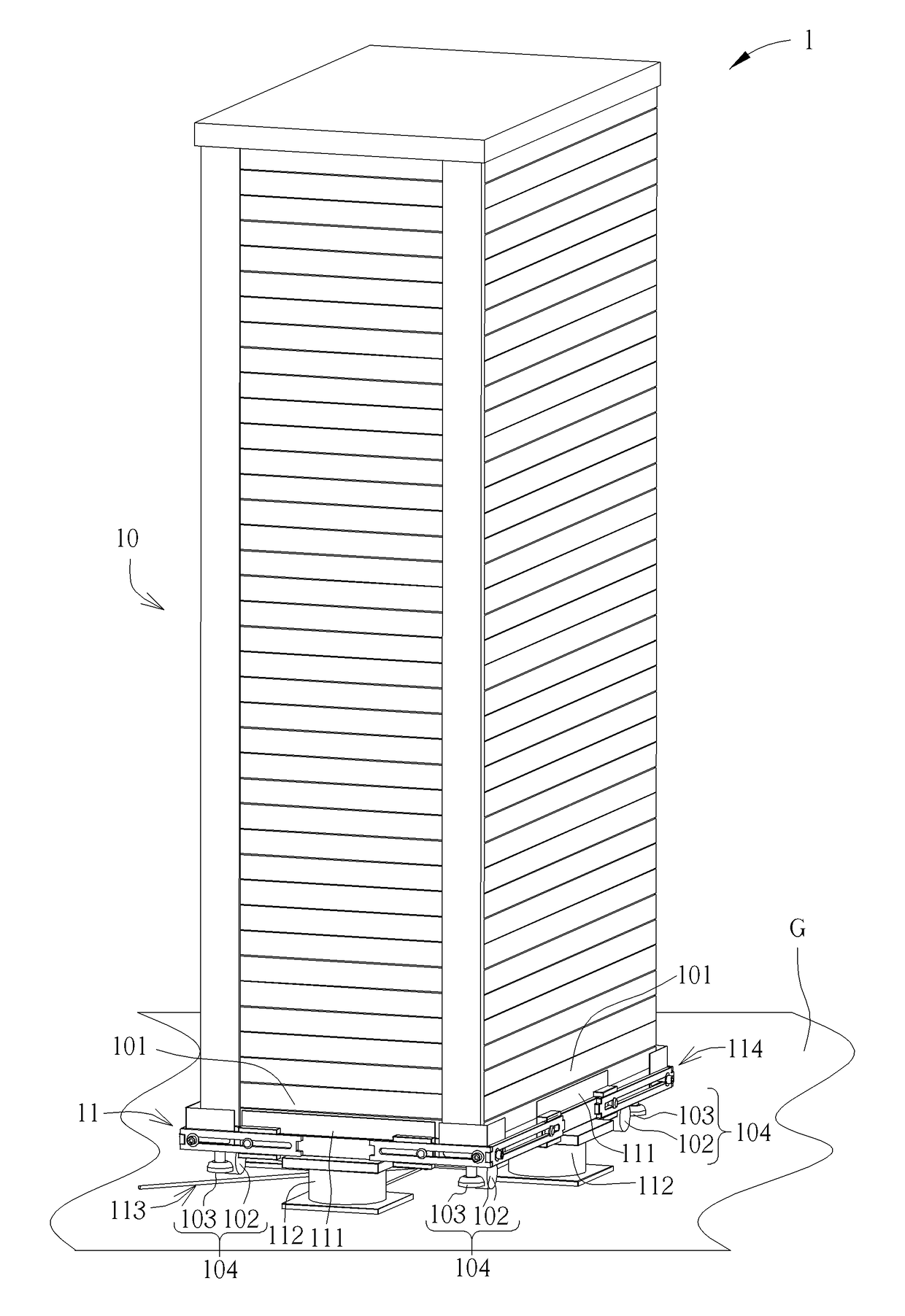
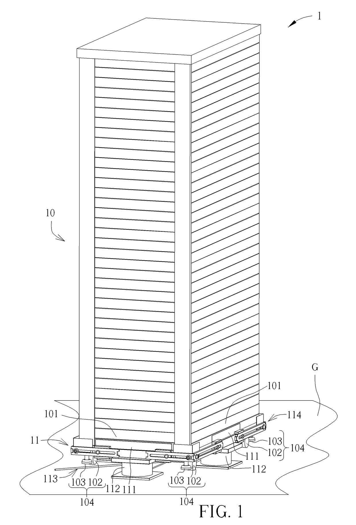
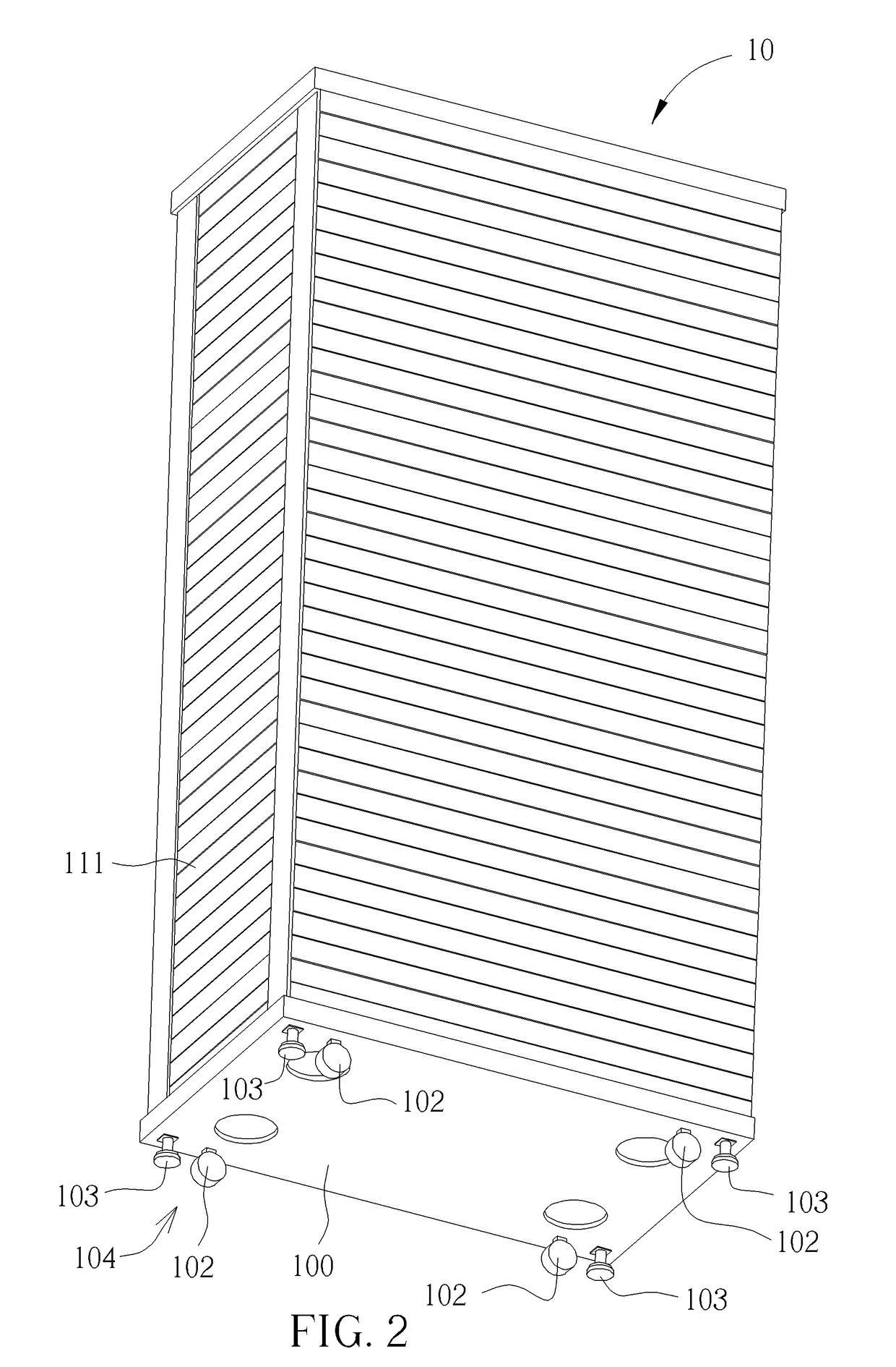
[0033]Please refer to FIG. 1 and FIG. 2. FIG. 1 is a schematic diagram of a cabinet device 1 according to a first embodiment of the present disclosure. FIG. 2 is a diagram of a cabinet 10 according to the first embodiment of the present disclosure. As shown in FIG. 1 and ...


PUM


Abstract

A pallet structure includes at least one bottom plate and at least one air bag. The at least one bottom plate is disposed on a bottom side of the cabinet for supporting the cabinet. The at least one air bag is detachably installed on a bottom side of the at least one bottom plate. The at least one air bag is inflated to prop the at least one bottom plate against the cabinet upwardly until at least one supporting component of the cabinet leaves away from a supporting surface, so as to effectively absorb a shock load during transportation of the cabinet.

Description

BACKGROUND OF THE INVENTION1. Field of the Invention[0001]The present disclosure relates to a pallet structure and a cabinet device, and more particularly, to a pallet structure with air bag structure, which is capable of effectively absorbing a shock load during transportation of a cabinet, a cabinet device therewith, and a method thereof.2. Description of the Prior Art[0002]Transportation of a batch of cabinets by a container at one time can effectively reduce transportation cost. However, the cabinets may be damaged easily because of shock loads during transportation. Therefore, the current solution is to dispose a high density foam component between a pallet and a cabinet for absorbing shock loads during transportation of the cabinet, which prevents damage of a server in the cabinet. However, in order to unload the cabinet from the container to a predetermined location, it normally requires a manual forklift, a forklift truck, and a slope. The manual forklift is utilized to move...

Claims


Application Information

Patent Timeline
IPC IPC(8): B65D19/40B65D19/00A47B91/00A47B91/06
CPCB65D19/40B65D19/0012A47B91/005B65D2519/0086B65D2519/00781B65D2519/00786A47B91/06B65D19/44B65D81/022B65D2519/00273B65D2519/00293B65D2519/00323B65D2519/00761B65D2519/00815B65D2585/647
Inventor JIANG, JHENG-YING
Owner WIWYNN CORP
Why Eureka
Try Eureka