Variable flux allocation within a lidar fov to improve detection in a region

a technology of variable flux allocation and lidar fov, which is applied in the direction of process and machine control, using reradiation, instruments, etc., can solve the problems of thermal damage to the retina and limited maximum illumination power of lidar systems

Active Publication Date: 2018-04-26
INNOVIZ TECH LTD
View PDF2 Cites 198 Cited by
  • Summary
  • Abstract
  • Description
  • Claims
  • Application Information

AI Technical Summary

Benefits of technology

[0011]Consistent with a disclosed embodiment, a LIDAR system may include at least one processor configured to: control at least one light source in a manner enabling light flux to vary over scans of a field of view using light from the at least one light source; control at least one light deflector to deflect light from the at least one light source in order to scan the field of view; receive from at least one sensor, reflections signals indicative of light reflected from objects in the field of view; determine, based on the reflections signals of an initial light emission, whether an object is located in an immediate area of the LIDAR system and within a threshold distance from the at least one light deflector, wherein the threshold distance is associated with a safety distance, and when no object is detected in the immediate area, control the at least one light source such that an additional light emission is projected toward the immediate area, thereby enabling detection of objects beyond the immediate area; when an object is detected in the immediate area, regulate at least one of the at least one light source and the at least one light deflector to prevent an accumulated energy density of the light in the immediate area to exceed a maximum permissible exposure.
[0014]Consistent with a disclosed embodiment, a LIDAR system may include at least one processor configured to: access an optical budget stored in memory, the optical budget being associated with at least one light source and defining an amount of light that is emittable in a predetermined time period by the at least one light source; receive information indicative of a platform condition for the LIDAR system; based on the received information, dynamically apportion the optical budget to a field of view of the LIDAR system based on at least two of: scanning rates, scanning patterns, scanning angles, spatial light distribution, and temporal light distribution; and output signals for controlling the at least one light source in a manner enabling light flux to vary over scanning of the field of view in accordance with the dynamically apportioned optical budget.
[0017]Consistent with a disclosed embodiment, a LIDAR system, may include at least one processor configured to: control at least one light source in a manner enabling light flux of at least one light source to vary over a plurality of scans of a field of view, the field of view including a near-field portion and a far-field portion; control at least one light deflector to deflect light from the at least one light source in a manner scanning the field of view; implement a first scanning rate for first frames associated with scanning cycles that cover the near-field portion and a second scanning rate for second frames associated with scanning cycles that cover the far-field portion, wherein the first scanning rate is greater than the second rate; and control the at least one light source, after projecting light that enables detection of objects in a plurality of sequential first frames associated with the near-field portion, to alter a light source parameter and thereby project light in a manner enabling detection of objects in the second frames associated with the far-field portion.
[0018]Consistent with a disclosed embodiment, a LIDAR system for use in a vehicle may include at least one processor configured to: control at least one light source in a manner enabling light flux of at least one light source to vary over scans of a field of view; control at least one light deflector to deflect light from the at least one light source in order to scan the field of view; receive input indicative of a current driving environment of the vehicle; and based on the current driving environment, coordinate the control of the at least one light source with the control of the at least one light deflector to dynamically adjust an instantaneous detection distance by varying an amount of light projected and a spatial light distribution of light across the scan of the field of view.
[0019]Consistent with a disclosed embodiment, a LIDAR system for use in a vehicle may include at least one processor configured to: control at least one light source in a manner enabling light flux of light from at least one light source to vary over a scanning cycle of a field of view; control at least one deflector to deflect light from the at least one light source in order to scan the field of view; obtain input indicative of an impending cross-lane turn of the vehicle; and in response to the input indicative of the impending cross-lane turn, coordinate the control of the at least one light source with the control of the at least one light deflector to increase, relative to other portions of the field of view, light flux on a side of the vehicle opposite a direction of the cross-lane turn and encompassing a far lane of traffic into which the vehicle is merging, and causing a detection range opposing the direction of the cross-lane turn of the vehicle to temporarily exceed a detection range toward a direction of the cross-lane turn.

Problems solved by technology

Currently, however, the maximum illumination power of LIDAR systems is limited by the need to make the LIDAR systems eye-safe (i.e., so that they will not damage the human eye which can occur when a projected light emission is absorbed in the eye's cornea and lens, causing thermal damage to the retina.)

Method used


Image

  • Variable flux allocation within a lidar fov to improve detection in a region
  • Variable flux allocation within a lidar fov to improve detection in a region
  • Variable flux allocation within a lidar fov to improve detection in a region

Examples


example implementation

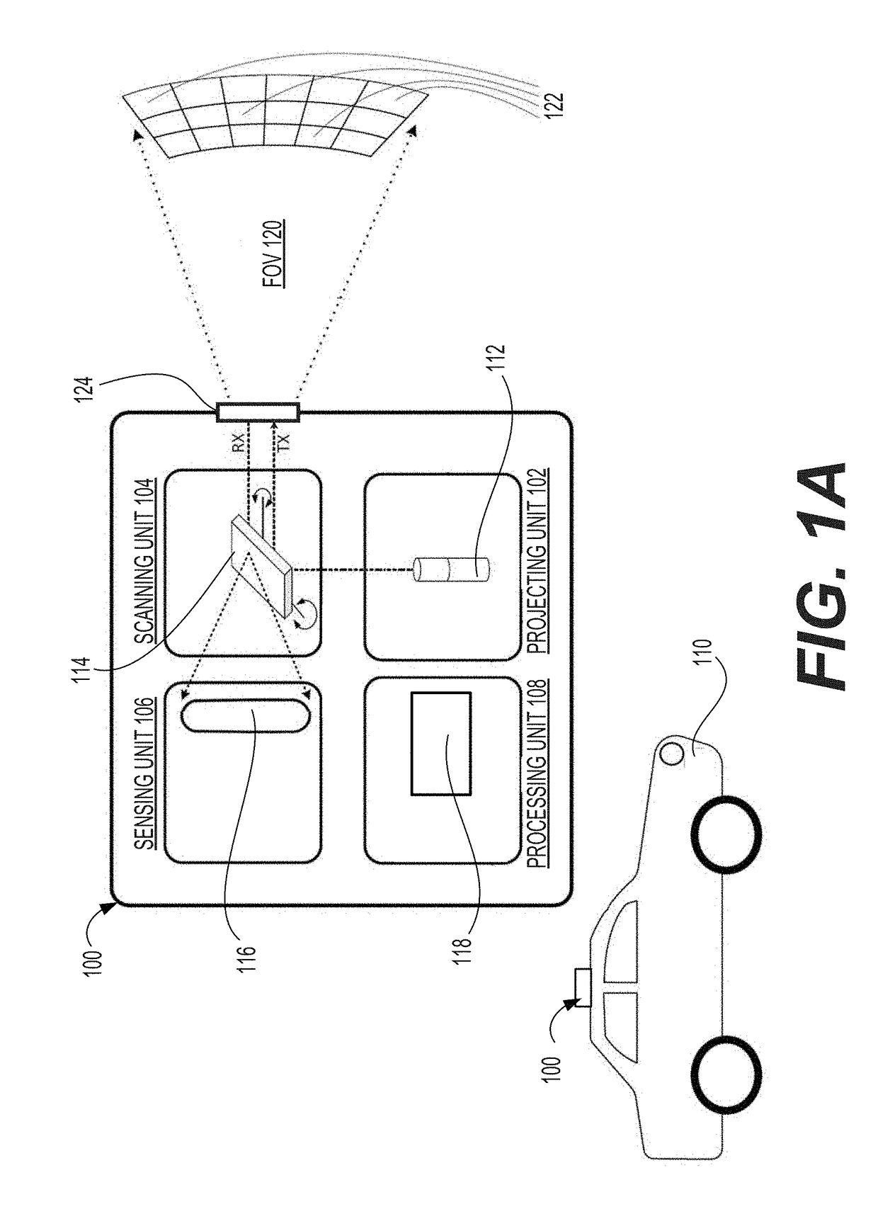
[0202]FIG. 6D illustrates the implementation of LIDAR system 100 in a surveillance system. As mentioned above, LIDAR system 100 may be fixed to a stationary object 650 that may include a motor or other mechanisms for rotating the housing of the LIDAR system 100 to obtain a wider field of view. Alternatively, the surveillance system may include a plurality of LIDAR units. In the example depicted in FIG. 6D, the surveillance system may use a single rotatable LIDAR system 100 to obtain 3D data representing field of view 120 and to process the 3D data to detect people 652, vehicles 654, changes in the environment, or any other form of security-significant data.

[0203]Consistent with some embodiment of the present disclosure, the 3D data may be analyzed to monitor retail business processes. In one embodiment, the 3D data may be used in retail business processes involving physical security (e.g., detection of: an intrusion within a retail facility, an act of vandalism within or around a re...


PUM


Abstract

A LIDAR system is provided. The LIDAR system comprises at least one processor configured to: control at least one light source in a manner enabling light intensity to vary over a scan of a field of view using light from the at least one light source; control at least one light deflector to deflect light from the at least one light source; obtain an identification of at least one distinct region of interest in the field of view; and increase light allocation to the at least one distinct region of interest relative to other regions, such that following a first scanning cycle, light intensity in at least one subsequent second scanning cycle at locations associated with the at least one distinct region of interest is higher than light intensity in the first scanning cycle at the locations associated with the at least one distinct region of interest.

Description

CROSS REFERENCES TO RELATED APPLICATIONS[0001]This application claims the benefit of priority of U.S. Provisional Patent Application No. 62 / 396,858, filed Sep. 20, 2016; U.S. Provisional Patent Application No. 62 / 396,863, filed Sep. 20, 2016; U.S. Provisional Patent Application No. 62 / 396,864, filed Sep. 20, 2016; U.S. Provisional Patent Application No. 62 / 397,379, filed Sep. 21, 2016; U.S. Provisional Patent Application No. 62 / 405,928, filed Oct. 9, 2016; U.S. Provisional Patent Application No. 62 / 412,294, filed Oct. 25, 2016; U.S. Provisional Patent Application No. 62 / 414,740, filed Oct. 30, 2016; U.S. Provisional Patent Application No. 62 / 418,298, filed Nov. 7, 2016; U.S. Provisional Patent Application No. 62 / 422,602, filed Nov. 16, 2016; U.S. Provisional Patent Application No. 62 / 425,089, filed Nov. 22, 2016; U.S. Provisional Patent Application No. 62 / 441,574, filed Jan. 3, 2017; U.S. Provisional Patent Application No. 62 / 441,581, filed Jan. 3, 2017; U.S. Provisional Patent Appl...

Claims


Application Information

Patent Timeline
Patent Type & Authority Applications(United States)
IPC IPC(8): G01S7/48G01S17/02G01S17/66G01S7/484G01S17/06G01S17/89G01S7/491G01S7/486G01S7/4861G01S7/4863G01S17/04G01S17/10G01S17/93G01S17/931
CPCG01S17/42G01S7/4817G01S7/4808G01S17/58G01S17/04G01S17/894G01S17/931G02B26/0858G02B26/10G01S17/89G01S7/4812G05D1/024G08G1/166B60Q1/26G08G1/04G01S7/484G01S7/4814G01S7/4861B60Q1/0023G01S7/497G01S7/4876G01S7/4863G01S7/4815G05D2201/0212B60W2420/52G01S17/10G01S7/4868G01S7/4972G01S17/93G05D2201/0213G01S7/486
Inventor STEINBERG, AMITBERMAN, PAVELELOOZ, DAVIDZOHAR, GUYKREMER, HANOCHVLAIKO, JULIANOSIROFF, NIRKEILAF, OMER DAVIDBUSKILA, ORENROSENZWEIG, ORENESHEL, RONEN
Owner INNOVIZ TECH LTD
Why Eureka
Try Eureka