Multi-fiber optical connector

a fiber optic connector and fiber technology, applied in the field of multi-fiber optical connectors, can solve the problems of low workability at the time of connecting each fiber and the need for a certain amount of fiber length, and achieve the effects of high workability, simple structure and convenient assembly

Inactive Publication Date: 2018-04-26
NAMIKI PRECISION JEWEL CO LTD
View PDF2 Cites 1 Cited by
  • Summary
  • Abstract
  • Description
  • Claims
  • Application Information

AI Technical Summary

Benefits of technology

[0016]According to the present invention, it is possible to provide a multi-fiber optical connector in which the connector can be easily assembled by having a simple structure and high workability is provided by the plate-shaped guide at, the time of connection. In other words, according to the multi-fiber optical connector described in the present application, used is a structure in which a connector ferrule is adopted as the plate-shaped guide by applying drilling processing to a plate member. Therefore, a main portion can be formed only by inserting a fiber into the plate-shaped guide at the time of assembling the connector, and assembly thereof can be easily performed. Additionally, positioning accuracy can be improved in use as a connector by forming the plate-shaped guide as a single component serving as a guide of each fiber. This effect can be obtained in addition to the above effects because each of the fibers can be mutually moved in the optical axis direction at the time of connecting the connectors, and a tip portion of each of the fibers is held in a movable state.
[0017]More specifically, as for the holding structure, the gap is provided on the rear surface of the plate-shaped guide in the present invention, thereby absorbing a buckling amount caused by movement of each fiber and also elastically supporting the tip portion by using resilience of the bucking portion. Therefore, according to the present invention, fibers can be used in a state that a projecting length each thereof generated at a tip of the multi-fiber optical connector is different from each other. Additionally, according to the present invention, a buckling amount caused by contacting and pressurizing between tip portions of fibers facing each other is absorbed in the gap at the time of connecting the connectors. More specifically, the fiber is moved in the optical axis direction along the penetration hole provided at the plate-shaped guide due to the structure. Therefore, fiber cores that can be elastically connected in a manner independent from each other can be collectively and elastically connected by aligning positions of plate-shaped guides. Meanwhile, as an alignment method between the plate-shaped guides, a method of providing a positioning pin in each of the plate-shaped guides or a method of providing a positioning fixing member in the connector itself may be exemplified. Additionally, since the above-described elastic connection is used, respective fibers can be collectively connected without applying highly accurate polishing to tip portions of the fibers.
[0018]Furthermore, in the present invention, the projecting length of the fiber is set to a length in which fiber core connection can be kept by the penetration hole provided at the plate-shaped guide. More specifically, the projecting length is the length in which loss of each fiber core with respect to a facing fiber core is suppressed within a certain range at the time of connecting the connectors, and connection can be kept by movement inside the penetration hole. Since an angle of the penetration hole is also processed in a similar range, the multi-fiber optical connector of the present invention can connect respective fiber cores each other with low loss even in the state that projecting lengths are different from each other as described above.
[0019]In addition to the above-mentioned effects, used in the present invention is the structure in which the abutting surface is partly formed in the plate-shaped guide for mutual abutment. Therefore, when a positioning pin and the like is used at the time of connecting the connectors, fiber cores can be mutually connected with high accuracy and positioning accuracy can be easily improved. The effects are provided by the structure partly including the abutting surface. In other words, in the present embodiment, the reference surfaces are aligned with high accuracy by using the abutting surface as reference surfaces for plate-shaped guides facing each other at the time of connection when positioning for the plate-shaped guides are to be performed. Furthermore, since the abutting surface is only partly formed, effects can be obtained in which a processing amount of the abutting surface that requires high surface accuracy is reduced and a protruding amount of a fiber can be easily set at the time of connecting the connectors. Additionally, workability at the time of connecting the connectors can be significantly improved by the above-described positioning as well as the entire structure including the abutting surface.
[0020]Moreover, by using the present invention, the gap is protected from mixture of a foreign matter and reliability as a connector can be improved while keeping the above-described functions and effects.
[0021]As described above, according to the present invention, it is possible to provide a multi-fiber optical connector which can be easily assembled by having the simple structure and provides high workability at the time of connection.

Problems solved by technology

In such a transmission medium in the related art, each of the fibers is connected by fusion splice, and while respective fiber cores to be connected can be coaxially fixed with high accuracy, there may be disadvantages in which workability at the time of connecting each fiber is low and a length of a fiber is needed to have a certain amount of margin because of a method thereof.

Method used


Image

  • Multi-fiber optical connector
  • Multi-fiber optical connector
  • Multi-fiber optical connector

Examples


Embodiment Construction

[0026]In the following, the best embodiment of the present invention will be described using FIGS. 1, 2, 3, and 4.

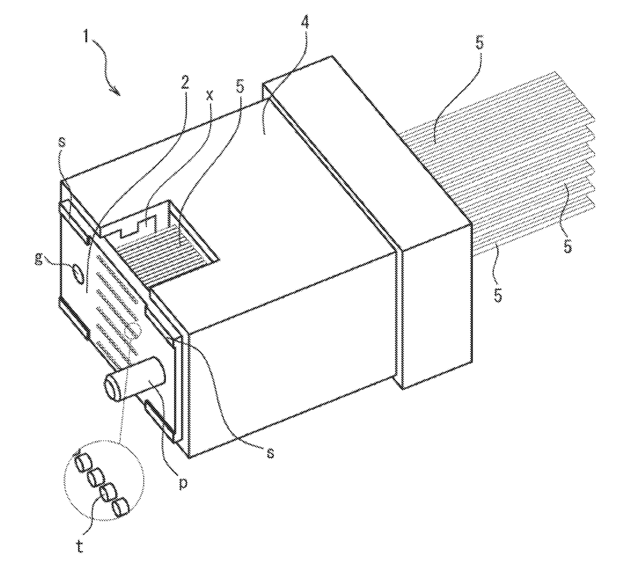
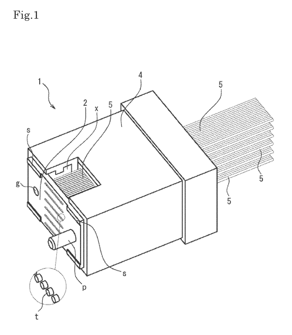
[0027]FIG. 1 is a perspective view of an entire multi-fiber optical connector used in the present embodiment, FIG. 2 is an exploded perspective view of the multi-fiber optical connector, FIG. 3 is a side cross-sectional explanatory view illustrating a structure inside the connector when the multi-fiber optical connector is connected, and FIG. 4 is an exploded perspective view of the multi-fiber optical connector, respectively. Note that illustration of a rear end portion of a fiber is omitted in the drawings.

[0028]As illustrated in FIGS. 1, 2, and 3, a multi-fiber optical connector 1 according to the present embodiment includes a plate-shaped guide 2, a fiber guide 3, and a holder 4, and has a structure in which a tip portion t of a fiber 5 inserted into a penetration hole h provided inside the plate-shaped guide 2 from a rear end side of the multi-fiber optical connecto...


PUM


Abstract

Provided is a multi-fiber optical connector which can be easily assembled by having a simple structure an provides high workability at the time of connection.Since a plate-shaped guide 2 adapted to move a fiber is provided on an end surface and a gap x is provided on a rear surface of the plate-shaped guide 2, achieved is a structure in which each of fibers 5 is mutually moved in an optical axis direction along a penetration hole h provided at the plate-shaped guide 2 at the time of connecting connectors. Consequently, the respective fibers 5 which can be elastically connected independently from each other can be collectively connected at the time of connecting the connectors, and furthermore, positioning accuracy between the respective fibers 5 can be improved when the connector is used as a multi-fiber optical connector 1.

Description

TECHNICAL FIELD[0001]The present invention relates to a multi-fiber optical connector attached to one end of an optical cable and adapted to collectively connect a plurality of fibers.BACKGROUND ART[0002]Presently, a transmission medium in which a plurality of optical fibers such as a tape core wire and an optical cable are bundled are widely used in the field of optical communication. In such a transmission medium in the related art, each of the fibers is connected by fusion splice, and while respective fiber cores to be connected can be coaxially fixed with high accuracy, there may be disadvantages in which workability at the time of connecting each fiber is low and a length of a fiber is needed to have a certain amount of margin because of a method thereof. Considering such situations, recently used are multi-fiber optical connectors represented by JP 4032973 B (hereinafter referred to as Patent Literature and JP 5462080 B (hereinafter referred to as Patent Literature 2). Here, t...

Claims


Application Information

Patent Timeline
Patent Type & Authority Applications(United States)
IPC IPC(8): G02B6/38
CPCG02B6/3885G02B6/3839G02B6/3809G02B6/38
Inventor ABUMI, MASAHIROIKEGAI, KAZUAKIODA, NOBUHIKOHAYASHI, TAKEHIRO
Owner NAMIKI PRECISION JEWEL CO LTD
Why Eureka
Try Eureka