
Vision-Aided Inertial Navigation with Loop Closure

a technology of inertial navigation and loop closure, applied in navigation instruments, distance measurement, instruments, etc., can solve the problems of limited image feature location accuracy, wheel slip in a robot, and all forms of odometry suffer from accumulated errors

Active Publication Date: 2018-04-26
CHARLES STARK DRAPER LABORATORY
View PDF0 Cites 12 Cited by
  • Summary
  • Abstract
  • Description
  • Claims
  • Application Information

AI Technical Summary

Benefits of technology

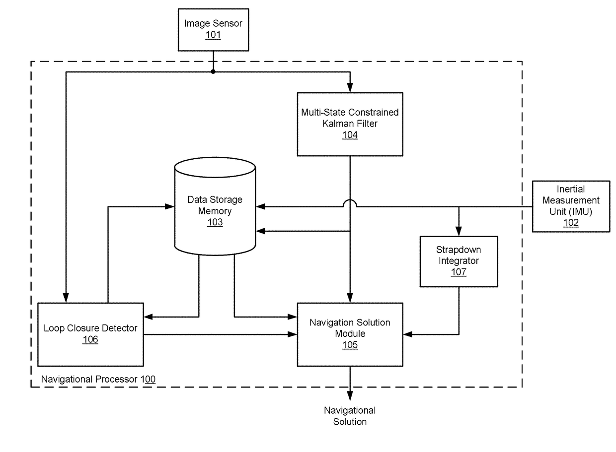
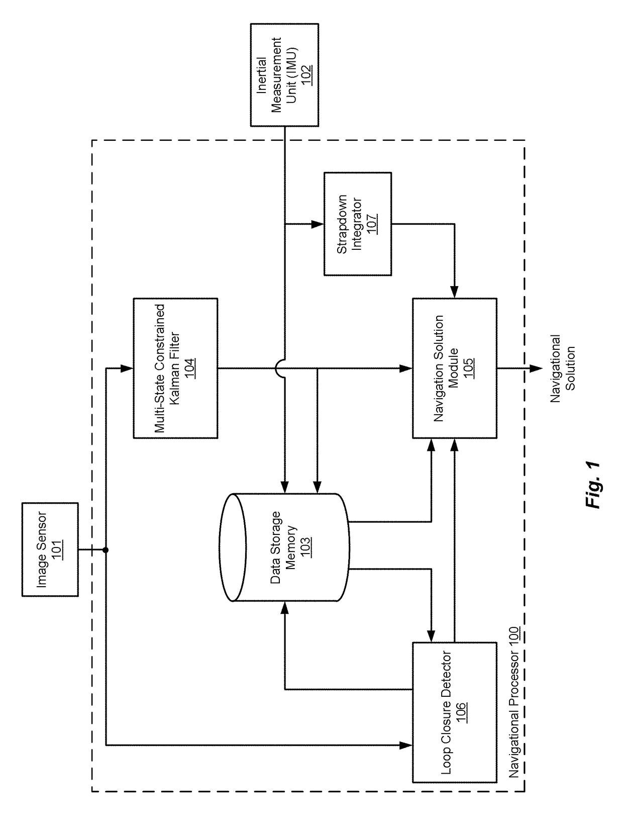
The present invention is a computer-implemented system that helps determine navigation solutions for a traveling vehicle using image and inertial information. It includes an image sensor and an inertial measurement unit sensor that collects data. The system uses a multi-state constraint Kalman filter to analyze the image sensor poses and estimates the vehicle's position and orientation. A strapdown integrator analyzes the inertial navigation information to estimate the vehicle's changing location. A navigation solution module analyzes the image sensor poses and inertial navigation solutions to produce a time sequence of navigation solutions that represent the vehicle's changing location. A loop closure detector classifies the navigation images and the navigation solution output is reset to a previous location when the detector classifies an incoming navigation image as loop-closing. The system uses a convolutional neural network for loop closure detection and a feed-forward image classification method. The navigation solution module produces the navigation solutions in pose graph form and calculates a six degree-of-freedom covariance for use with the image classification. Overall, the invention provides a reliable and efficient solution for vehicle navigation in various environments.

Problems solved by technology

However, all forms of odometry suffer from accumulated error.
For example, wheel slip in a robot introduces error, because the robot does not travel as far as rotation of the wheel indicates.
Similarly, location accuracy of a feature within an image is limited by resolution of the camera that captured the image.
Furthermore, because odometry estimates a current position from an estimated distance traveled from a previously estimated position, any error in any of the position or distance estimates accumulates.
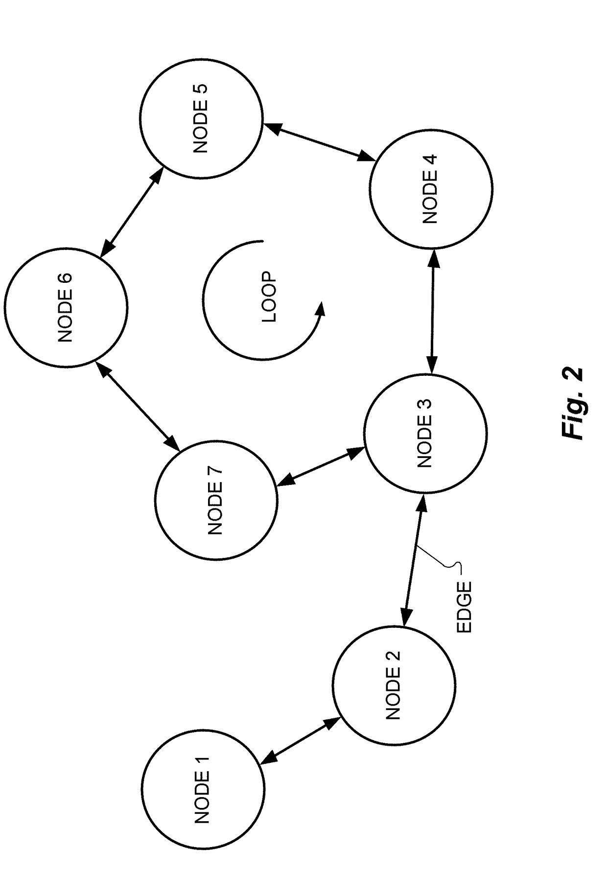
However, loop closure poses problems, at least because a transform between the camera pose of the loop closure image and the camera pose of the matching image is not known in all six degrees of freedom.

Method used


Image

  • Vision-Aided Inertial Navigation with Loop Closure
  • Vision-Aided Inertial Navigation with Loop Closure
  • Vision-Aided Inertial Navigation with Loop Closure

Examples


Embodiment Construction

[0017]Visual odometry as in a vision aided inertial navigation system involves analysis of optical flow, for example, using a Lucas-Kanade algorithm. Optical flow is the pattern of apparent motion of objects, surfaces, and edges in a visual scene caused by the relative motion between an observer (such as a camera) and the scene. Embodiments of the present invention modify the Lucas-Kanade method as implemented in a multi-state constraint Kalman filter (MSCKF) arrangement.

[0018]Vision odometry systems slowly accumulate navigational error. Embodiments of the present invention are directed to reducing or eliminating accumulated error in a visual-aided inertial navigation system for a traveling vehicle by resetting the system navigation solution whenever the system determines that the vehicle has returned to a previous location. This determination involves a process referred to as loop closure. The system stores navigation images and estimated navigation solutions that are associated wi...


PUM


Abstract

A vision-aided inertial navigation system determines navigation solutions for a traveling vehicle. A navigation solution module analyzes image sensor poses and estimated inertial navigation solutions to produce a time sequence of system navigation solution outputs that represent changing locations of the traveling vehicle. A loop closure detector performs a two-threshold image classification to classify an incoming navigation image as novel, loop-closing, or neither, and the navigation solution module resets the navigation solution output to represent a previous location when the loop closure detector classifies an incoming navigation image as loop-closing.

Description

[0001]This application claims priority to U.S. Provisional Patent Application 62 / 413,251, filed Oct. 26, 2016, which is incorporated herein by reference in its entirety.STATEMENT REGARDING FEDERALLY SPONSORED RESEARCH OR DEVELOPMENT[0002]This invention was made with Government support under Contract Number W56KGU-14-C-00035 awarded by the U.S. Army (RDECOM, ACC-APG CERDEC). The U.S. Government has certain rights in the invention.TECHNICAL FIELD[0003]The present invention relates to vision-aided inertial navigation.BACKGROUND ART[0004]Odometry is the use of data from motion sensors to estimate changes in position over time. For example, a wheeled autonomous robot may use rotary encoders coupled to its wheels to measure rotations of the wheels and estimate distance and direction traveled along a factory floor from an initial location. Thus, odometry estimates position and / or orientation relative to a starting location. The output of an odometry system is called a navigation solution.[...

Claims


Application Information

Patent Timeline
Patent Type & Authority Applications(United States)
IPC IPC(8): G05D1/02G01C21/16G01C22/00
CPCG05D1/0253G01C21/165G05D1/0272G01C22/00G05D1/027G01C21/1656
Inventor MADISON, RICHARD W.STICH, MELANIE K.
Owner CHARLES STARK DRAPER LABORATORY
Learn More