Workpiece conductive feature inspecting method and workpiece conductive feature inspecting system

a technology of workpieces and features, applied in the direction of image enhancement, image analysis, instruments, etc., can solve the problems of large amount of manpower required for inspection tasks, difficult identification of soldering points formed by soldering, and difficulty in identifying soldering points, so as to reduce the length of computing time, compare the amount and computing time for comparing features images and predetermined feature points, and achieve the effect of reducing the burden on computing devices

Inactive Publication Date: 2018-04-26
INVENTEC PUDONG TECH CORPOARTION +1
View PDF2 Cites 3 Cited by
  • Summary
  • Abstract
  • Description
  • Claims
  • Application Information

AI Technical Summary

Benefits of technology

[0006]One aspect of the present invention is to provide a method for inspecting conductive features of a workpiece. According to the present invention method, the standard workpiece image is divided into the plurality of standard workpiece sub-images having a smaller area and less predetermined feature points, and the standard workpiece sub-images are compared with the workpiece sub-image that is obtained by capturing image of part of the workpiece and has the features images corresponding to

Problems solved by technology

Traditionally, a large amount of manpower is required when soldering electronic components on circuit boards or other electronic products.
In addition to the process used for soldering, it is more difficult to identify the soldering points formed by soldering.
However, during the process of manufacturing, it is inevitable to generate defects, and thus manpower is still required to carry out the inspection tasks.
With the soldering of the circuit boards or other electronic products becoming increasingly complex, the inspection tasks, which yet ca

Method used


Image

  • Workpiece conductive feature inspecting method and workpiece conductive feature inspecting system
  • Workpiece conductive feature inspecting method and workpiece conductive feature inspecting system
  • Workpiece conductive feature inspecting method and workpiece conductive feature inspecting system

Examples


Embodiment Construction

[0027]Reference will now be made in detail to the present embodiments of the invention, examples of which are illustrated in the accompanying drawings. Wherever possible, the same reference numbers are used in the drawings and the description to refer to the same or like parts.

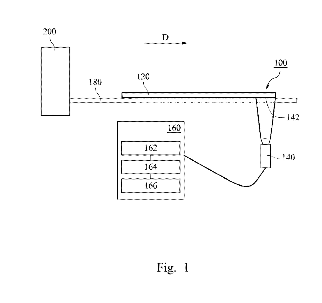
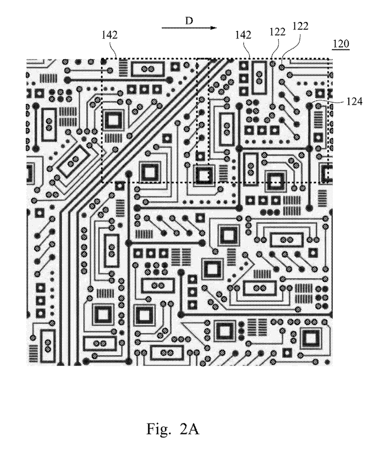
[0028]FIG. 1 depicts a simple schematic diagram of a system for inspecting conductive features of a workpiece 100 according to various embodiments of this invention. FIG. 2A depicts a bottom view of a workpiece 120 in the system for inspecting conductive features of the workpiece 100 according to various embodiments of this invention. As shown in FIG. 1, the system for inspecting conductive features of the workpiece 100 may comprise the workpiece 120, a video capture tool 140, a computing device 160, and a production line 180. A description is provided with reference to FIG. 2A. In various embodiments, the workpiece 120 may comprise conductive features formed on a surface of the workpiece 120. In other embodim...


PUM


Abstract

A method for inspecting conductive features of a workpiece includes videographing a part of a workpiece having a plurality of conductive features to capture a workpiece sub-image, in which the workpiece sub-image has one or more feature images respectively corresponding to one or more of the conductive features; finding predetermined feature points corresponding to a part of the feature images among a plurality of predetermined feature points based on the predetermined feature points in a standard workpiece image to locate an area of the standard workpiece image corresponding to the workpiece sub-image; and comparing the corresponding area of the standard workpiece image with the workpiece sub-image, if one or more of the predetermined feature points within the area differ from the one or more first feature images, the workpiece is determined to be a defective workpiece.

Description

RELATED APPLICATIONS[0001]This application claims priority to Chinese Application Serial Number 201610914663.3, filed Oct. 20, 2016, which is herein incorporated by reference.BACKGROUNDField of Invention[0002]The present invention relates to a method for inspecting conductive features of a workpiece and a system for inspecting conductive features of a workpiece. More particularly, the present invention relates to a method for inspecting conductive features of a workpiece and a system for inspecting conductive features of a workpiece applied to an inspection process in a production line.Description of Related Art[0003]Traditionally, a large amount of manpower is required when soldering electronic components on circuit boards or other electronic products. In addition to the process used for soldering, it is more difficult to identify the soldering points formed by soldering. Therefore, it is necessary to use more manpower for quality control to check whether soldering points on circui...

Claims


Application Information

Patent Timeline
IPC IPC(8): G06T7/00
CPCG06T7/001G06T2207/30152G06T2207/30141
Inventor CHEN, YONG-CHENG
Owner INVENTEC PUDONG TECH CORPOARTION
Why Eureka
Try Eureka