High speed injector with two stage turbulence flap

a high-speed injector and flap technology, which is applied in the directions of mixing, transportation and packaging, papermaking, etc., can solve the problems of more turbulence and better mixing of fluids

Active Publication Date: 2018-05-03
ANDRITZ AB
View PDF2 Cites 2 Cited by
  • Summary
  • Abstract
  • Description
  • Claims
  • Application Information

AI Technical Summary

Benefits of technology

[0010]It is an object of the solution to address at least some of the problems outlined above. It is possi

Problems solved by technology

This results in a velocity increase right before the injection point, as well as a velocity increase after the mix

Method used


Image

  • High speed injector with two stage turbulence flap
  • High speed injector with two stage turbulence flap
  • High speed injector with two stage turbulence flap

Examples


Embodiment Construction

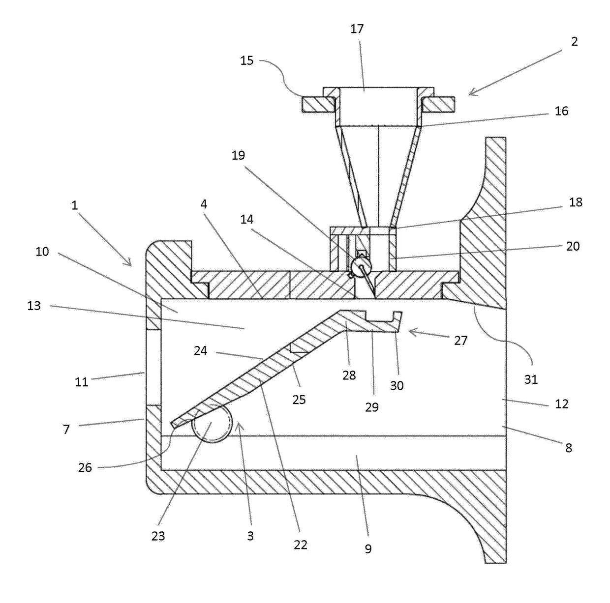
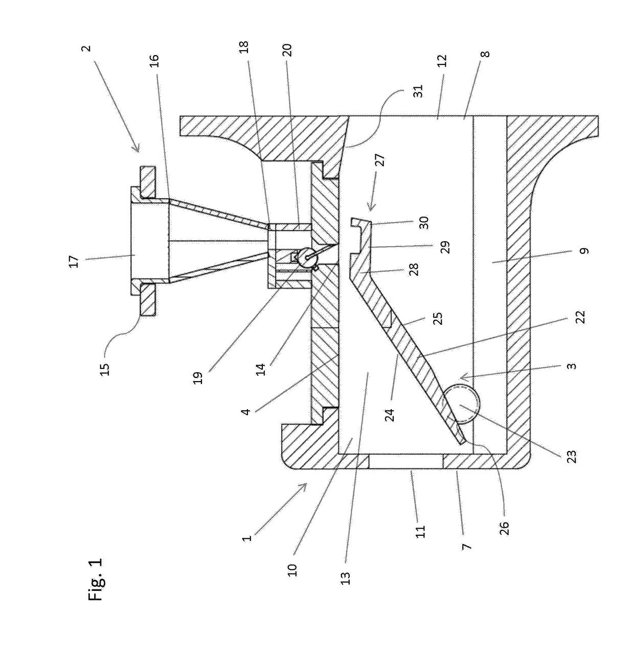
[0027]The embodiment of the invention that will be described in the following is intended to be used in a process plant for mixing a second fluid, in the form of steam, into the flow path of a first fluid, in the form of a cellulose pulp suspension, wherein the hot steam is intended for heating the pulp suspension to a desired temperature, e.g. to a temperature that is suitable for a subsequent bleaching step. It will be appreciated, however, that the principle of the invention may be used for mixing other fluids, such as gases, e.g. oxygen gas, chlorine gas or ozone, or liquids, e.g. pH-adjusting liquids, chlorine dioxide or other treatment liquid, into a pulp suspension. It will also be appreciated that the first fluid may be of another type than a pulp suspension, e.g. process liquor.

[0028]The apparatus comprises a substantially parallelepipedic housing 1, for receiving a pulp suspension from a first conduit, as well as for discharging the pulp suspension into a second conduit lo...


PUM

PropertyMeasurementUnit
Fractionaaaaaaaaaa
Forceaaaaaaaaaa
Flow rateaaaaaaaaaa

Abstract

An apparatus comprising a chamber enclosing a flow path of a first fluid and having a second inlet arranged downstream of the first inlet for receiving a second fluid. The apparatus further comprises a vertically adjustable throttle body an end portion comprising three parts, the first part being upstream of the second part, the third part being downstream of the second part, wherein, in an operating position, the second inlet is upstream of the third part of the throttle body and downstream of the first inlet and wherein the first part and the third part of the end portion are adapted to achieve a higher flow rate than the second part.

Description

TECHNICAL FIELD[0001]The present invention relates to an apparatus and a method for mixing a first fluid with a second fluid, particularly for mixing steam into pulp.BACKGROUND ART[0002]As used herein, fluid means a gas, a liquid, a steam or a mixture of these. As used herein, the notion fluid is also mean to include a system consisting of a mixture of solid particles and a liquid or gas, where the mixture has fluid-like properties. One example of such a system is a suspension, e.g. a cellulose pulp suspension.[0003]As used herein, introducing one fluid into the flow path of another fluid means injection, mixing, dispersion or other admixing of one fluid, which is also called the admixture fluid, into the flow path of the other fluid.[0004]It is not unusual in industrial processes that fluids are mixed with each other. In e.g. the paper industry, it is not unusual that process chemicals, e.g. oxygen gas, chlorine dioxide or ozone, are introduced into a flow of pulp suspension. It is...

Claims


Application Information

Patent Timeline
IPC IPC(8): B01F5/04B01F3/04B01F5/06D21C9/10
CPCB01F5/0473B01F3/04503B01F5/0611D21C9/1005B01F2215/0078B01F23/2323B01F25/314B01F25/3141B01F25/4311B01F25/431973Y10T137/0357Y10T137/87652B01F35/2211B01F35/833B01F23/20B01F23/23B01F25/00B01F2101/47
Inventor LINDSTROM, ANDERSLAM S, AXEL
Owner ANDRITZ AB
Why Eureka
Try Eureka