Fuel stabilization chamber

Inactive Publication Date: 2018-05-03
HAMILTON SUNDSTRAND CORP
View PDF7 Cites 20 Cited by
  • Summary
  • Abstract
  • Description
  • Claims
  • Application Information

AI Technical Summary

Problems solved by technology

Further, the dissolved oxygen within the fuel may react with fuel and form solids tha

Method used


Image

  • Fuel stabilization chamber
  • Fuel stabilization chamber
  • Fuel stabilization chamber

Examples


Embodiment Construction

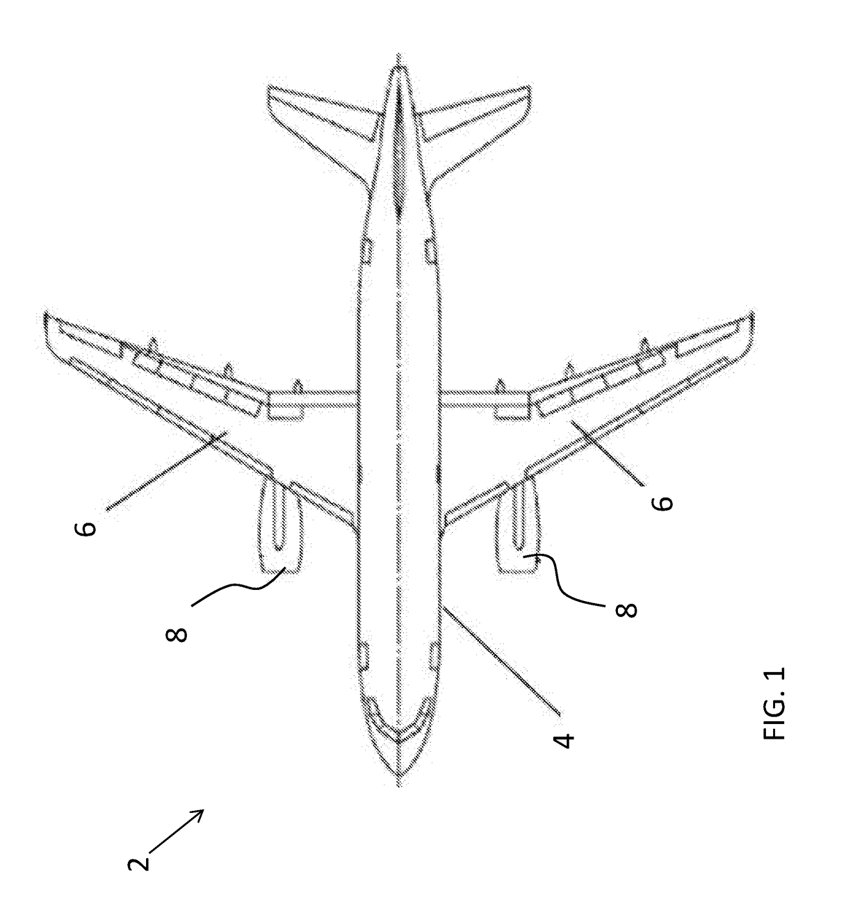
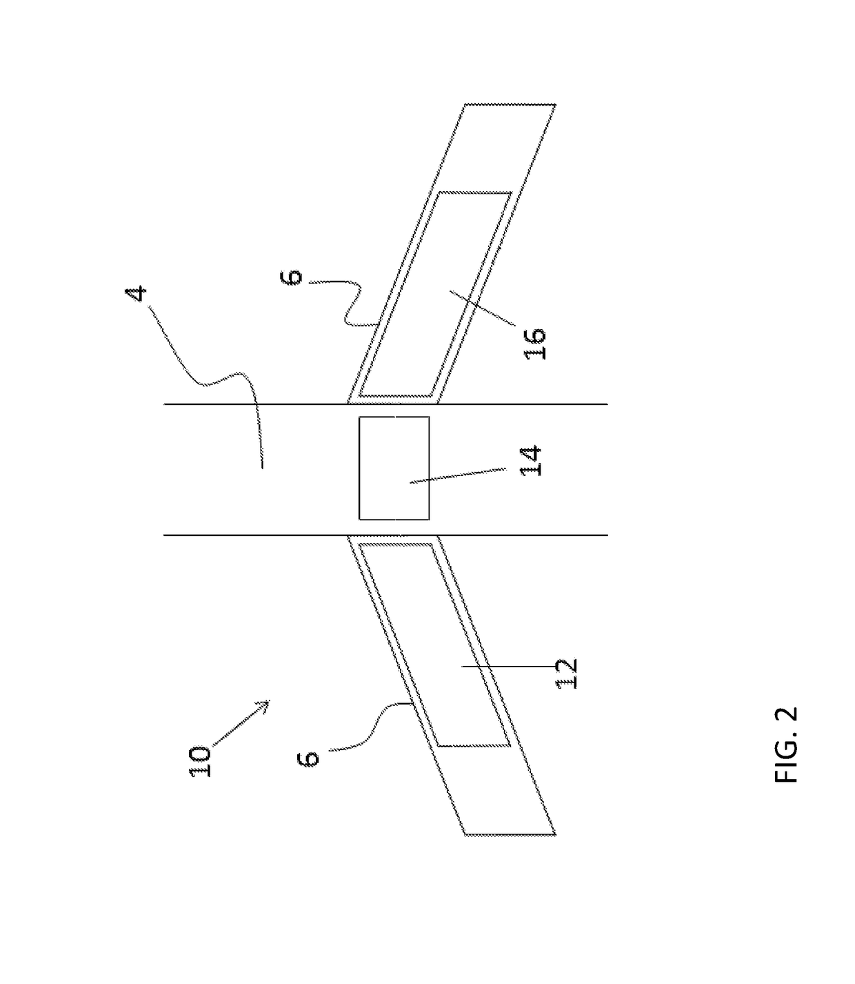
[0033]FIG. 1 is a plan view of an aircraft 2, such as a commercial airliner for example. The aircraft 2 includes a fuselage 4, a left and right wing 6, 6, and under-wing mounted engines 8. Arranged within an interior volume of the aircraft 2 is a fuel system having at least one fuel tank for storing aviation fuel. With reference to FIG. 2, the fuel tanks of a fuel system 10 having a three tank configuration are illustrated. As shown, the fuel system 10 includes a left wing tank 12, a right wing tank 16 and a center tank 14. The fuel system 10 additionally includes a ventilation system (not shown) for ventilating the ullage of each of the tanks 12, 14, 16. The fuel system 10 illustrated and described herein is intended as an example only, and other fuel systems having any number of tanks arranged in any configuration are also within the scope of the disclosure.

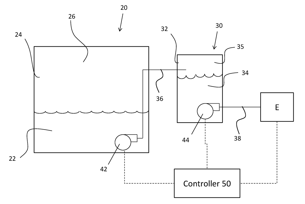
[0034]Referring now to FIGS. 3 and 4, an example of a tank 20 for use in a fuel system, such as fuel system 10 is illustrated...


PUM

PropertyMeasurementUnit
Temperatureaaaaaaaaaa
Volumeaaaaaaaaaa

Abstract

A system for generating inert gas comprising includes a fuel tank including an inner storage volume containing a fuel. A fuel stabilization chamber has an inner volume. The inner volume of said fuel stabilization chamber is arranged in fluid communication with the inner storage volume such that said fuel is movable from the inner storage volume to the inner volume. An inert gas device is operably coupled to the inner volume of the fuel stabilization chamber. Inert gas output from the inert gas device interacts with a fuel in the inner volume to remove dissolved oxygen from the fuel in said inner volume.

Description

CROSS-REFERENCE TO RELATED APPLICATIONS[0001]This application claims the benefit of Provisional Application Serial No. 62 / 414,855, filed Oct. 31, 2016, which is incorporated herein by reference in its entirety.BACKGROUND OF THE INVENTION[0002]This invention generally relates to the aircraft on-board systems, and more particularly, to a fuel stabilization system.[0003]On-board Inert Gas Generating Systems (OBIGGS) are used to introduce an inert gas into the fuel tanks of a vehicle, such as an aircraft. The inert gas displaces potentially dangerous fuel and air mixtures, thereby reducing the risk of explosion or fire. Further, the dissolved oxygen within the fuel may react with fuel and form solids that block the flow of fuel along the fuel passage and that foul heat exchange surfaces. Inert gas can be used to remove dissolved oxygen from fuel. Typically, OBIGGS process air from an air source, such as bleed air taken from the engines of an aircraft. A deoxygenated air is typically gen...

Claims


Application Information

Patent Timeline
IPC IPC(8): B64D37/32B64D37/08B01D53/047B01D53/22B01D53/32B01D19/00
CPCB64D37/32B64D37/08B01D53/047B01D53/22B01D53/32B01D19/0005A62C3/08B64D37/34
Inventor RHEAUME, JONATHANCORDATOS, HARALAMBOS
Owner HAMILTON SUNDSTRAND CORP
Why Eureka
Try Eureka