Warm-up system for exhaust gas apparatus

Active Publication Date: 2018-05-03
TOYOTA JIDOSHA KK
View PDF0 Cites 3 Cited by
  • Summary
  • Abstract
  • Description
  • Claims
  • Application Information

AI Technical Summary

Benefits of technology

The patent is about a system to maintain the temperature of an exhaust gas control catalyst in an internal combustion engine. By controlling the flow rate of exhaust gas through a turbine and while the temperature of the catalyst is controlled, the system can prevent a decrease in the catalyst's ability to control exhaust gas emissions. This leads to a suppression of exhaust gas control capacity decline and better engine performance.

Problems solved by technology

In an exhaust gas apparatus in which an exhaust gas control catalyst is disposed downstream of a turbine of a turbocharger a high heat capacity of the turbine tends to result in a deterioration of the warm-up property of the exhaust gas control catalyst.
Then, the warm-up property of the exhaust gas control catalyst may deteriorate.
As a result, the temperature of the warmed-up exhaust gas control catalyst may fall below the activation temperature of the exhaust gas control catalyst, and the exhaust gas control capacity of the exhaust gas control catalyst may decline.

Method used


Image

  • Warm-up system for exhaust gas apparatus
  • Warm-up system for exhaust gas apparatus
  • Warm-up system for exhaust gas apparatus

Examples


example 1

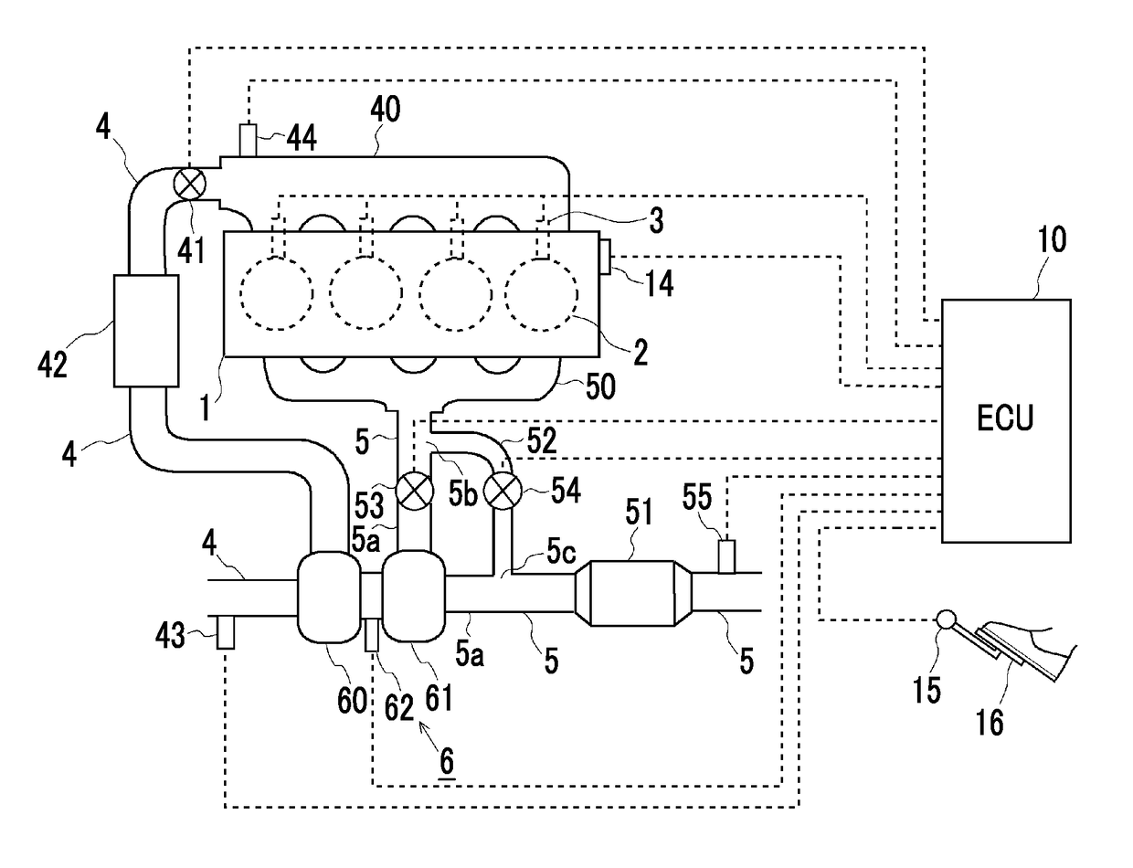
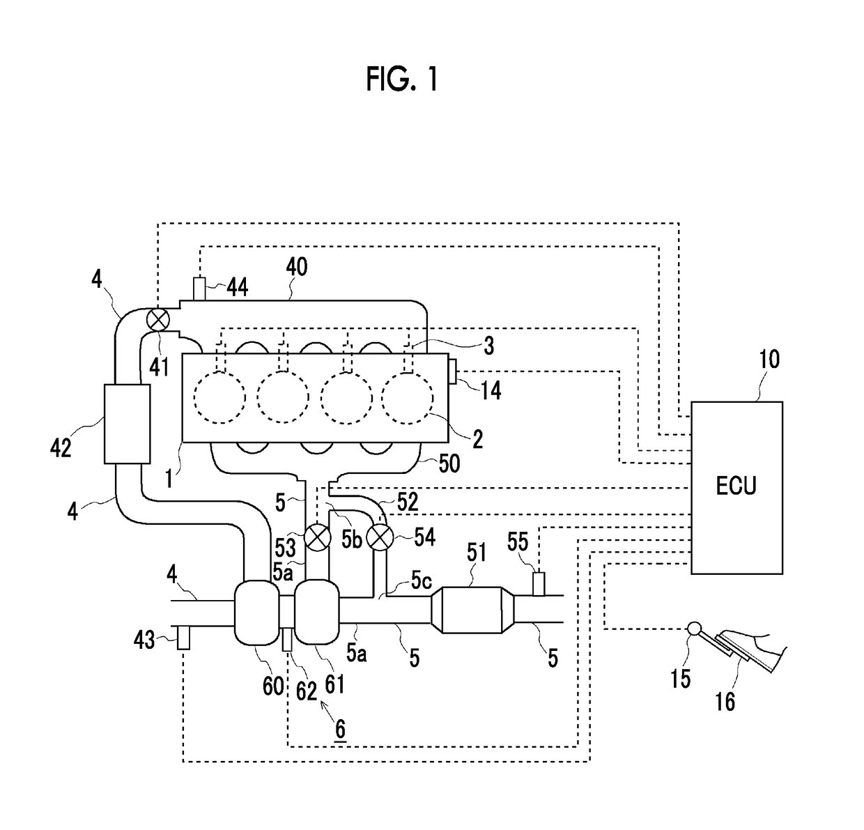
[0033]Hereinafter, a first example will be described with reference to accompanying drawings. FIG 1 is a diagram illustrating a schematic configuration of an internal combustion engine according to this example and a schematic configuration of an intake and exhaust system of the internal combustion engine. An internal combustion engine 1 illustrated in FIG. 1 is a spark ignition-type internal combustion engine (gasoline engine) that is provided with a cylinder group which includes four cylinders 2. Fuel injection valves 3 are disposed in the internal combustion engine 1, and the fuel injection valves 3 inject a fuel into respective intake ports. The fuel injection valves 3 may be configured to inject the fuel directly into the respective cylinders 2. Spark plugs (not illustrated) for igniting air-fuel mixtures in the cylinders are attached to the respective cylinders 2.

[0034]The internal combustion engine 1 is connected to an intake manifold 40 and an exhaust manifold 50. An intake ...

modification example

[0070]Hereinafter, a modification example of the first example described above will be described based on FIGS. 6 to 9. FIG. 6 is a diagram illustrating a schematic configuration of the internal combustion engine 1 according to this modification example and a schematic configuration of the intake and exhaust system of the internal combustion engine 1. As illustrated in FIG. 6, the TBV 53 and the WGV 54 are not disposed in an exhaust gas apparatus according to this modification example. In the exhaust gas apparatus, a distribution valve 56 is disposed in the merging portion 5c where the turbine side exhaust gas passage 5a and the bypass passage 52 merge with each other. A detailed description of substantially the same configuration and substantially the same control processing as in the first example described above will be omitted.

[0071]The distribution valve 56 that the exhaust gas apparatus according to this modification example is provided with is a distribution valve guiding the...

example 2

[0080]Hereinafter, a second example will be described based on FIGS. 10 to 12. FIG. 10 is a diagram illustrating a schematic configuration of the internal combustion engine 1 according to this example and a schematic configuration of the intake and exhaust system of the internal combustion engine 1. In an exhaust gas apparatus according to this example, a second exhaust gas control catalyst 57 is disposed on the exhaust gas passage 5 and provided downstream of the first exhaust gas control catalyst 51 as illustrated in FIG. 10. In addition, a second temperature sensor 58 is disposed on the exhaust gas passage 5 and provided downstream of the second exhaust gas control catalyst 57. A detailed description of substantially the same configuration and substantially the same control processing as in the first example described above will be omitted.

[0081]In the exhaust gas apparatus according to this example, the exhaust gas is controlled by the first exhaust gas control catalyst 51 and t...


PUM


Abstract

A warm-up system for an exhaust gas apparatus includes the exhaust gas apparatus having a turbocharger provided with a turbine, a first exhaust gas control catalyst provided downstream of the turbine, a bypass passage bypassing the turbine, and an adjustment unit adjusting a turbine inflow exhaust gas flow rate and an electronic control unit. The electronic control unit is configured to perform a warm-up control which warms the turbine by controlling the turbine inflow exhaust gas flow rate, by using the adjustment unit, to reach a flow rate higher than zero and lower than the post-warm-up flow rate when an operating state of the internal combustion engine remains constant, such that a warmed state of the first exhaust gas control catalyst is maintained after the first exhaust gas control catalyst is warmed.

Description

CROSS-REFERENCE TO RELATED APPLICATIONS[0001]This application claims priority to Japanese Patent Application No. 2016-212110 filed on Oct. 28, 2016 which is incorporated herein by reference in its entirety including the specification, drawings and abstract.BACKGROUND1. Technical Field[0002]The disclosure relates to a warm-up system for an exhaust gas apparatus in which an exhaust gas control catalyst is disposed downstream of a turbine of a turbocharger.2. Description of Related Art[0003]In an exhaust gas apparatus in which an exhaust gas control catalyst is disposed downstream of a turbine of a turbocharger a high heat capacity of the turbine tends to result in a deterioration of the warm-up property of the exhaust gas control catalyst.[0004]Known in this regard is a technique for opening a waste gate valve and conducting a bypass passage during a cold start of an internal combustion engine that is provided with a turbocharger, the bypass passage bypassing a turbine of the turbocha...

Claims


Application Information

Patent Timeline
IPC IPC(8): F02B37/18F01N11/00F01N3/20
CPCF02B37/18F01N11/002F01N3/2006F01N9/00F01N2900/14F01N2900/1404F01N2900/1626F01N2240/20F01N2340/06F01N2410/00F01N2410/06F01N2900/08F01N2900/1602F02B37/183Y02T10/12Y02T10/40
Inventor HOSOYA, TAKANOBUIRISAWA, YASUYUKIKUBOTA, HIROFUMITSUNOOKA, TAKASHI
Owner TOYOTA JIDOSHA KK
Why Eureka
Try Eureka