Device and method for detecting optical signal

Active Publication Date: 2018-05-03
ELECTRONICS & TELECOMM RES INST
View PDF8 Cites 3 Cited by
  • Summary
  • Abstract
  • Description
  • Claims
  • Application Information

AI Technical Summary

Benefits of technology

[0006]At least one example embodiment provides a large multichannel optical sign

Problems solved by technology

However, a process of manufacturing the substrate having th

Method used


Image

  • Device and method for detecting optical signal
  • Device and method for detecting optical signal
  • Device and method for detecting optical signal

Examples


Example

[0039]Hereinafter, some example embodiments will be described in detail with reference to the accompanying drawings. Regarding the reference numerals assigned to the elements in the drawings, it should be noted that the same elements will be designated by the same reference numerals, wherever possible, even though they are shown in different drawings. Also, in the description of embodiments, detailed description of well-known related structures or functions will be omitted when it is deemed that such description will cause ambiguous interpretation of the present disclosure.

[0040]The following detailed structural or functional description of example embodiments is provided as an example only and various alterations and modifications may be made to the example embodiments. Accordingly, the example embodiments are not construed as being limited to the disclosure and should be understood to include all changes, equivalents, and replacements within the technical scope of the disclosure.

[...


PUM


Abstract

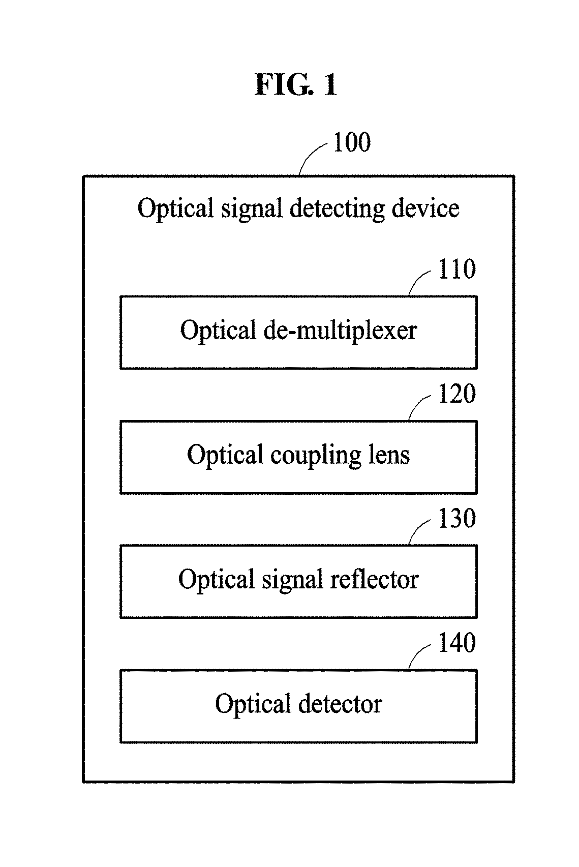
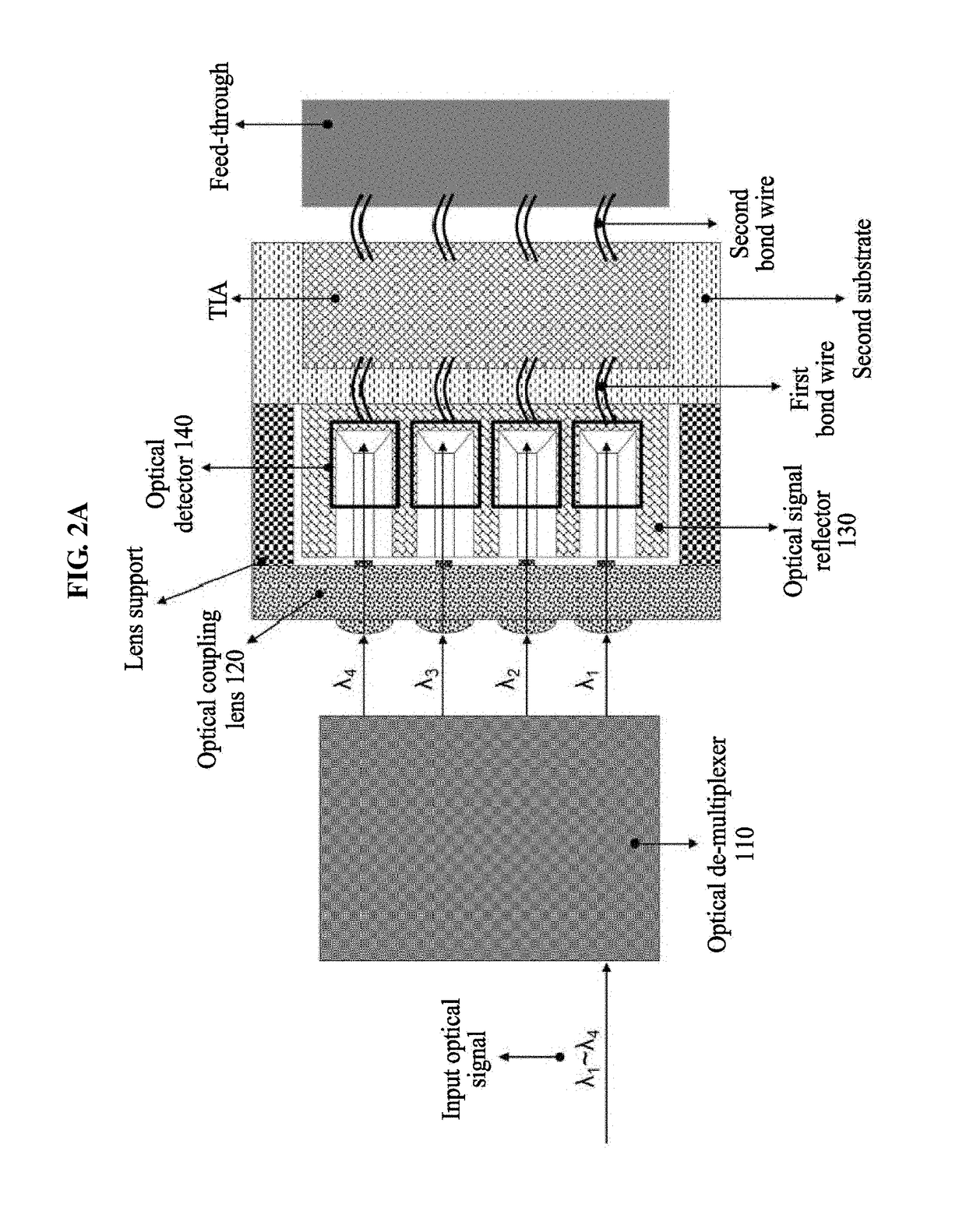
Provided is a device and method for detecting an optical signal. The optical signal detecting device may include an optical de-multiplexer configured to de-multiplex an input optical signal to optical signals of different wavelengths; an optical coupling lens configured to allow the optical signals of different wavelengths to be incident; an optical signal reflector configured to reflect the optical signals of different wavelengths emitted from the optical couple lens; and an optical detector configured to detect the reflected optical signals of different wavelengths.

Description

CROSS-REFERENCE TO RELATED APPLICATION(S)[0001]This application claims the priority benefit of Korean Patent Application No. 10-2016-0143182 filed on Oct. 31, 2016, and Korean Patent Application No. 10-2016-0160555 filed on Nov. 29, 2016 in the Korean Intellectual Property Office, the disclosure of which is incorporated herein by reference for all purposes.BACKGROUND1. Field[0002]One or more example embodiments relate to a device and method for detecting an optical signal.2. Description of Related Art[0003]An optical communication system includes a light transmitter configured to transform an electrical signal to an optical signal and a light receiver configured to receive the optical signal.[0004]In the optical communication system, a scheme of using a planar light wave circuit (PLC) and a scheme of using a thin film filter are generally employed for the light receiver.[0005]To this end, a substrate having a lateral pattern is required. However, a process of manufacturing the subst...

Claims


Application Information

Patent Timeline
IPC IPC(8): G02B6/293G02B6/42H04B10/67
CPCG02B6/2938G02B6/4214G02B6/4215G02B6/4249H04B10/67G02B6/4224
Inventor KANG, SAE-KYOUNGLEE, JOON KILEE, JIE HYUNHUH, JOON YOUNG
Owner ELECTRONICS & TELECOMM RES INST
Why Eureka
Try Eureka