
Biometric camera

a biometric and camera technology, applied in the field of biometric cameras, can solve the problems of insufficient accuracy of fingerprint identification systems, face and voice recognition systems, and can often be circumvented with relative ease, and add additional cost and additional space for a biometri

Active Publication Date: 2018-05-03
SAMSUNG ELECTRONICS CO LTD
View PDF1 Cites 48 Cited by
  • Summary
  • Abstract
  • Description
  • Claims
  • Application Information

AI Technical Summary

Benefits of technology

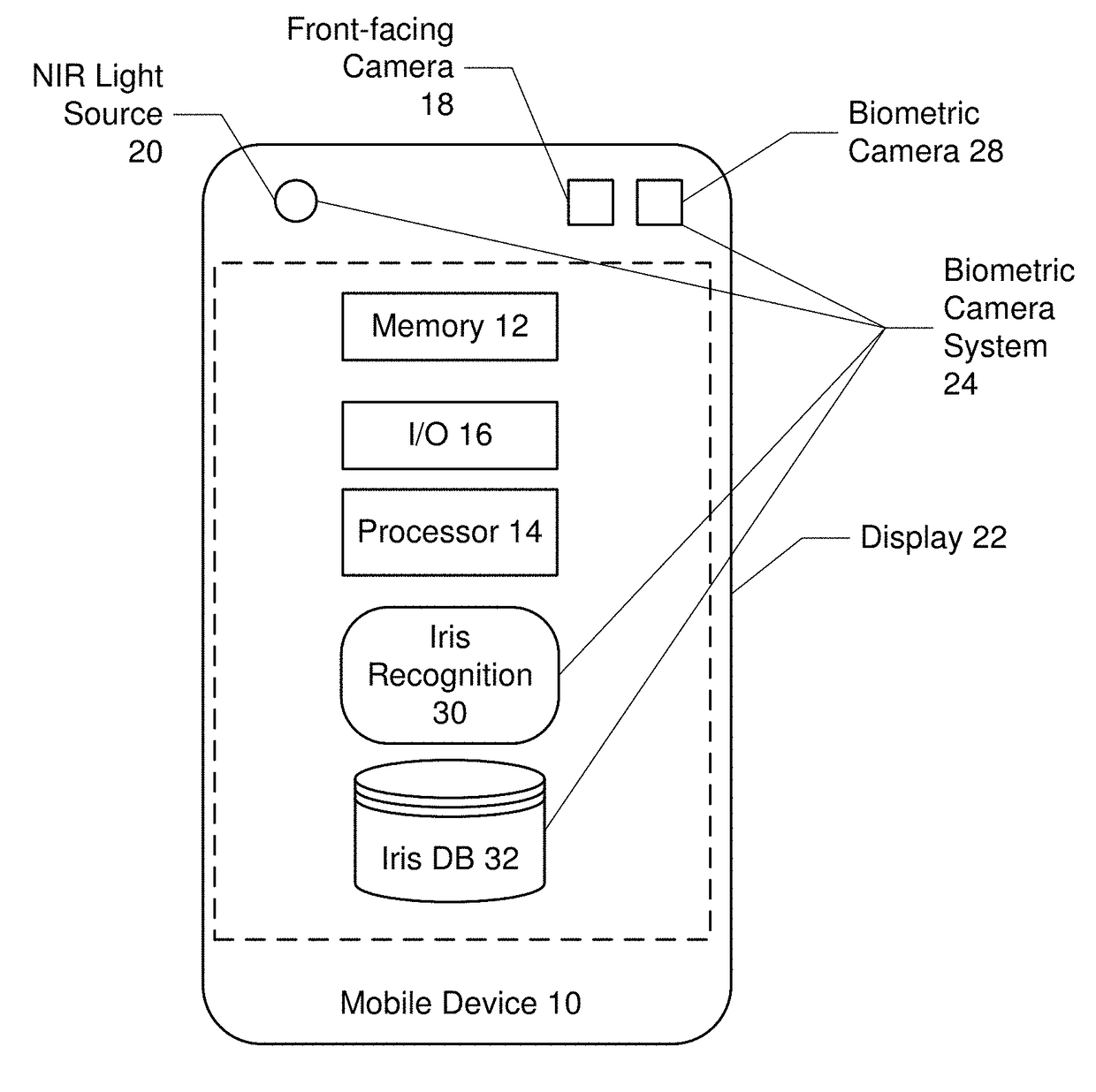
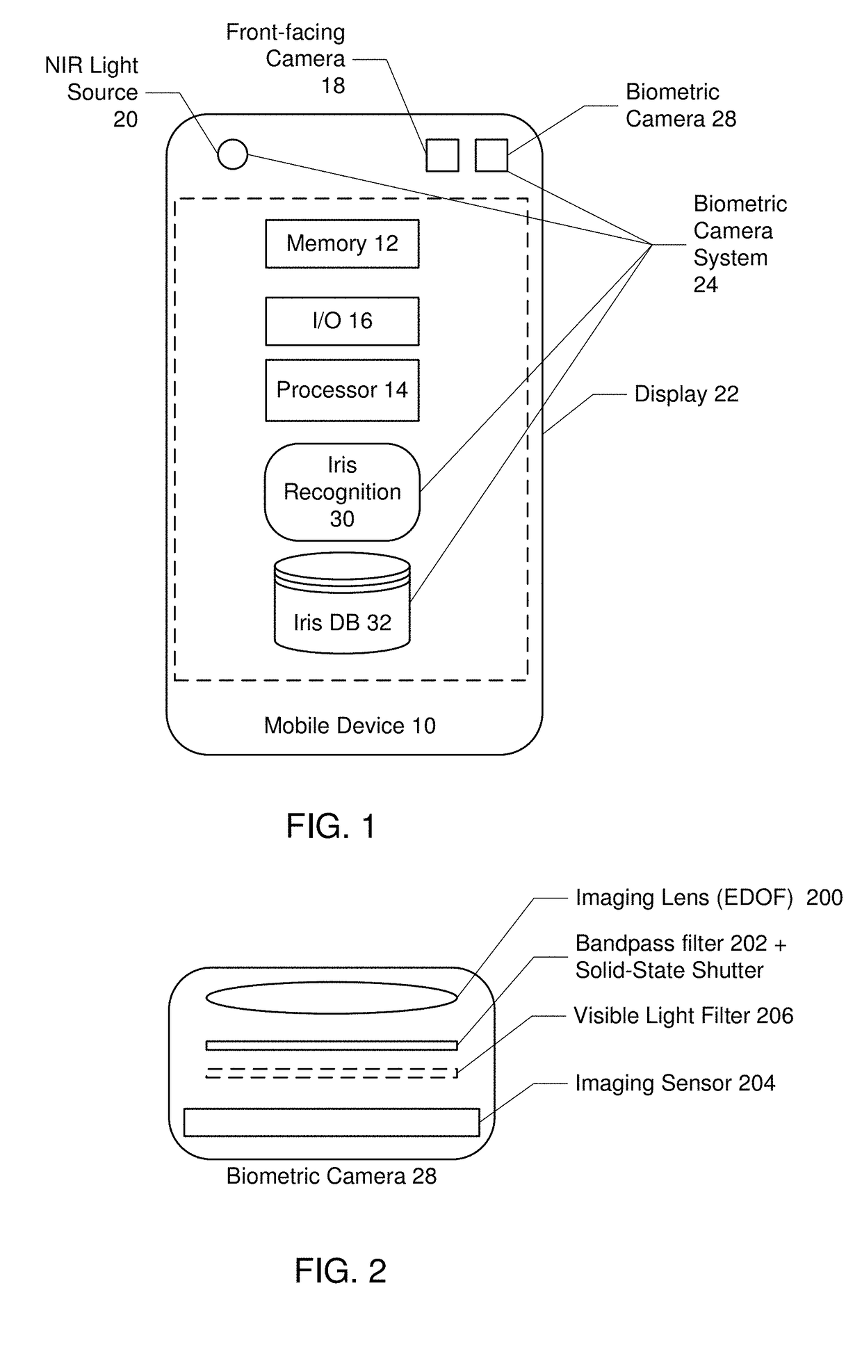
The invention is a biometric camera system for a mobile device. It includes a near infrared light source, a biometric camera, an extended depth of field imaging lens, a bandpass filter, and an imaging sensor. The camera system is designed to capture images of an user's iris and compare them to a database of registered images to authenticate the user. The technical effect of this invention is to provide a secure and accurate way to verify the identity of a user and access information on their mobile device.

Problems solved by technology

However, fingerprint identification systems suffer from the fact that users routinely leave fingerprints on various objects—and those fingerprints can be “lifted” and reproduced to circumvent fingerprint identification systems.
Also, face and voice recognition systems may not be sufficiently accurate and can often be circumvented with relative ease.
Such biometric camera systems face a number of challenges during their operation, including 1) ambient illumination (e.g. be able to operate in full sunlight); 2) motion blur (e.g. user's hand shaking while holding the smartphone and capturing iris); 3) depth of field at close distances (e.g. while taking pictures at short (“macro”) distances, the object being further or closer than the focused distance makes the image blurry); 4) additional cost and additional space for a biometric sensor; and 5) limited field of view (e.g., the camera must capture a high-resolution image of the iris for reliable identification.

Method used


Image

  • Biometric camera
  • Biometric camera
  • Biometric camera

Examples


Embodiment Construction

[0012]Reference will now be made in detail to the embodiments of the present general inventive concept, examples of which are illustrated in the accompanying drawings, wherein like reference numerals refer to the like elements throughout. The embodiments are described below in order to explain the present general inventive concept while referring to the figures.

[0013]Advantages and features of the present invention and methods of accomplishing the same may be understood more readily by reference to the following detailed description of embodiments and the accompanying drawings. The present general inventive concept may, however, be embodied in many different forms and should not be construed as being limited to the embodiments set forth herein. Rather, these embodiments are provided so that this disclosure will be thorough and complete and will fully convey the concept of the general inventive concept to those skilled in the art, and the present general inventive concept will only b...


PUM


Abstract

Exemplary embodiments for a biometric camera system for a mobile device, comprise: a near infrared (NIR) light source on the mobile device that flashes a user of the mobile device with near infrared light during image capture; a biometric camera located on the mobile device offset from the NIR light source, the biometric camera comprising: an extended depth of field (EDOF) imaging lens; a bandpass filter located adjacent to the EDOF imaging lens to reject ambient light during image capture; and an imaging sensor located adjacent the bandpass filter that converts an optical image of an object into an electronic signal for image processing; and a processor configured to receive video images of an iris of a user from the image sensor, and attempt to match the video images of the iris with previously registered images stored in an iris database, wherein if a match is found, the user is authenticated.

Description

CROSS-REFERENCE TO RELATED APPLICATIONS[0001]This application claims the benefit of Provisional Application Ser. No. 61 / 884,778, filed Sep. 30, 2013; Provisional Application Ser. No. 61 / 885,291, filed Oct. 1, 2013; and Provisional Application Ser. No. 61 / 913,620, filed Dec. 9, 2013, each assigned to the assignee of the present application, and incorporated herein by reference.BACKGROUND[0002]Mobile devices such as laptops—and most recently smartphones—have included biometric devices with the purpose of user identification. The biometric devices for example include fingerprint scanners, iris scanners and camera systems capable of face and / or voice recognition. However, fingerprint identification systems suffer from the fact that users routinely leave fingerprints on various objects—and those fingerprints can be “lifted” and reproduced to circumvent fingerprint identification systems. Also, face and voice recognition systems may not be sufficiently accurate and can often be circumvent...

Claims


Application Information

Patent Timeline
IPC IPC(8): G06K9/00G06F21/32
CPCG06K9/00604G06K9/00617G06K9/00033G06F21/32G06T7/586G07C9/00158G06K9/4609G06T2207/20201G07C9/37G06V40/19G06V40/197G06V40/1312
Inventor OVSIANNIKOV, ILIAPARK, YONG-HWACHO, YONG-CHULYOON, HEESUNPARK, CHANGYOUNGSMITS, DIRK
Owner SAMSUNG ELECTRONICS CO LTD
Learn More